

The following applies to Modbus devices.
Log in to EMX. Under the Manage tab, open the OPI drop down menu and click on OPI Templates.
Click on the ( + ) icon to expose the "Add Reading" dialog box. This will allow the addition of individual register points along with their characteristics.
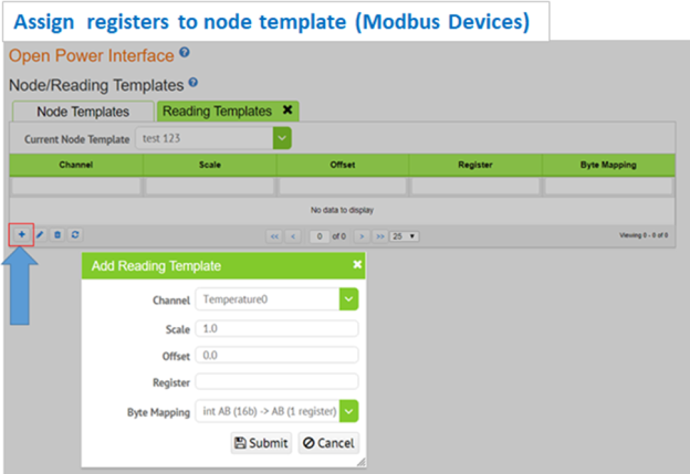
Complete all fields.
Channel: Designates the EMX channel that the register map shall be aligned with
Scale: The scaling factor or multiple applied to the register. Most device register maps will note the scaling factor of each register.
Offset: Offset implies where the register map starts. If the register map starts at 0 vs 1, each register may have an offset of 1.
Register: The actual register number from the device register map
Byte Mapping: The reading value is converted to a specified binary format, then mapped onto the specified set of 16-bit Modbus registers. The letters in the mapping denote bytes.
For example: "int ABCD (32b) => DC,BA (2 registers)"
This example will take a reading value, scale it, convert it to a 32 bit signed integer, then map it onto 2 consecutive Modbus registers while swapping bytes in each register.
Click the "Submit" box to save.
Continue to add registers using the ( + ) add register function until all the required registers are populated.
Editing existing registers
To edit an existing register, click on the pencil icon.