

The EMX panel editor is used in conjunction with our BGP and BGS products (branch circuit and multi-circuit monitors) to organize the readings so they correspond to the actual circuit mix coming out of your panels or equipment. For example, you can indicate that the three readings coming from the CTs on breakers 1, 2 and 3 should be combined into one 3-phase circuit (called a "virtual circuit"). You can give the virtual circuits names that make sense to you. Real-time readings can be viewed for the panel or for each virtual circuit.
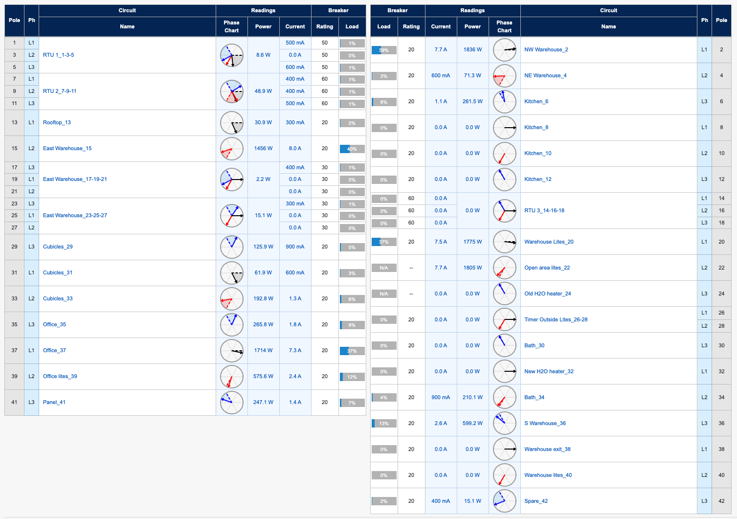
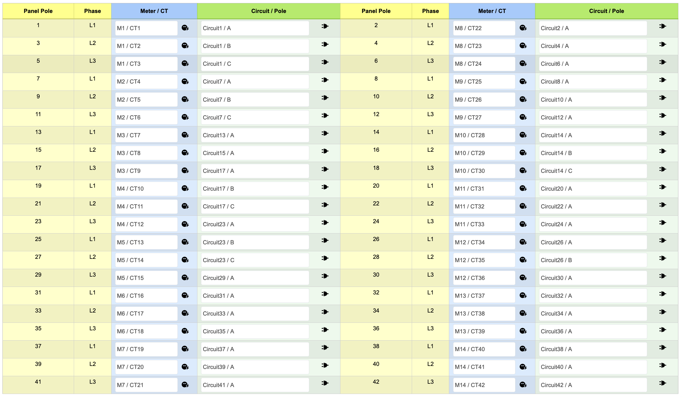
Here is the view of a panel with a mix of fully described circuits (also showing real time load).
To define your panel, you will need:
-
The 16-digit ID number of the BGPxx or BGSxx product being used to monitor that panel
-
A "panel schedule" that shows which circuits originate from the panel
-
Knowledge of which CTs were installed where on the panel.
The panel should already be available in your EMX account. To customize the panel you:
-
Edit the panel
-
Enable the panel
-
Access the data
Edit the panel
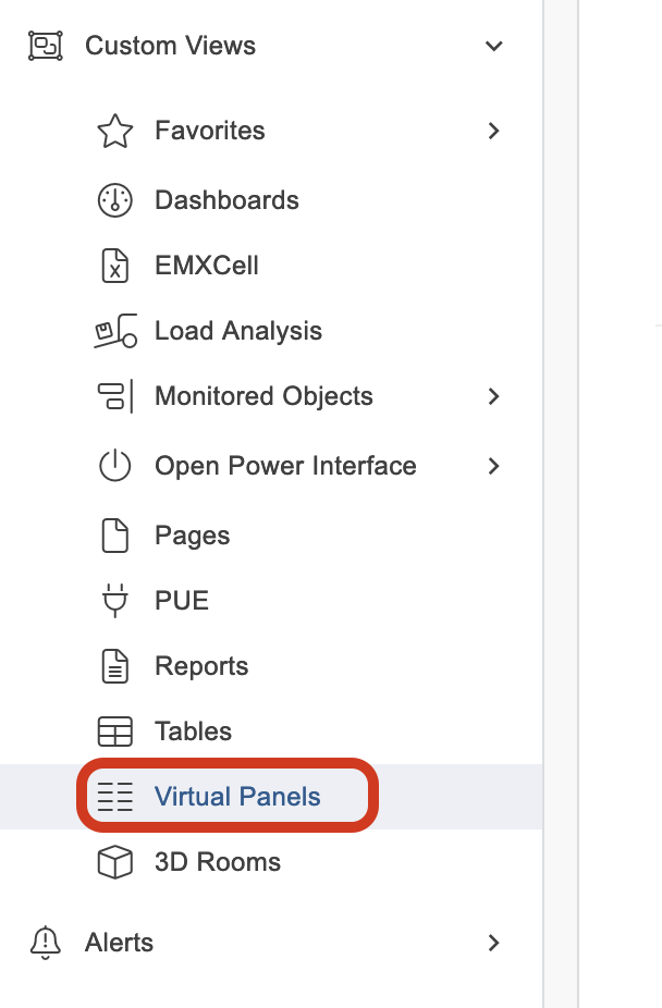
1. Log in to emx.packetpower.com. Go to Custom Views > Virtual Panels
2. Find the panel you want to edit in the table and click on it. Panels you have not yet edited can be identified by their Super GUID (the 16-digit GUID on the device enclosure).
Contact support@packetpower.com if your panel does not appear in the drop down list.
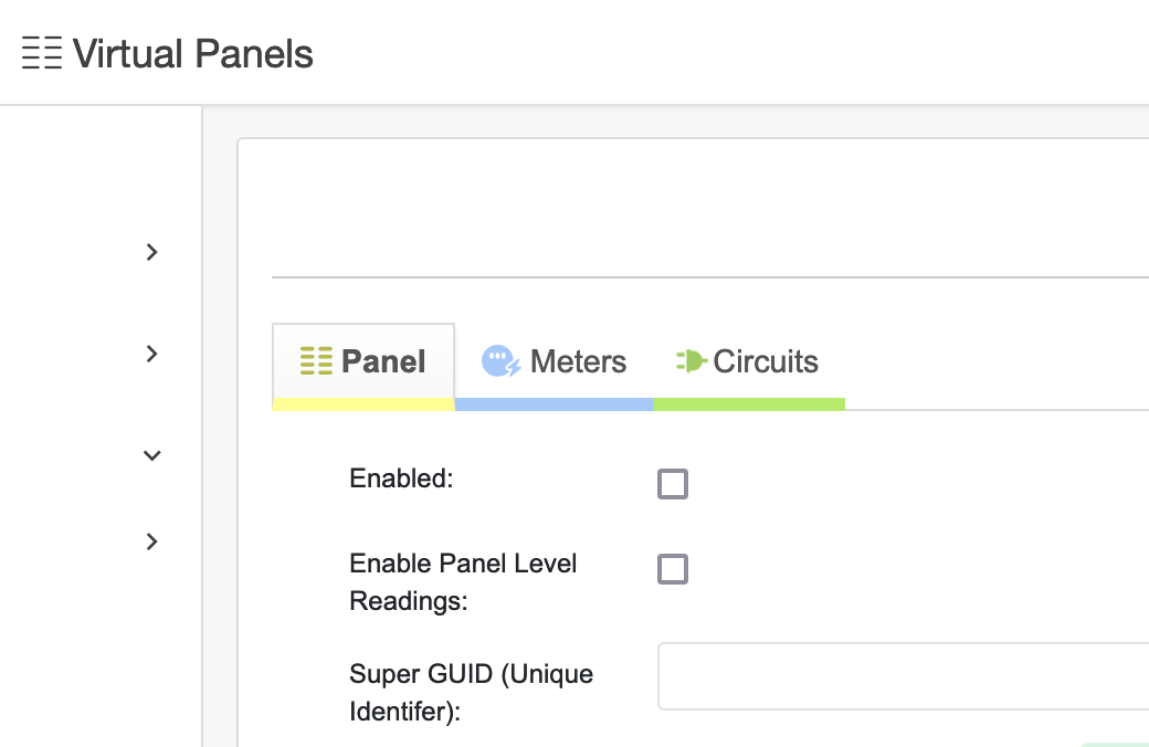
3. The panel edit screen has three tabs - Panel, Meters and Circuits.
-
The Panel tab shows high level information about the physical panel structure.
The only field in this tab that you will want to edit is the Panel name.
-
The Meters tab provides information about the physical meters installed in the Packet Power monitoring device. None of the fields in this tab should be edited.
-
The Circuits tab provides detailed information for each circuit in the panel. Circuit level information is added in this tab.
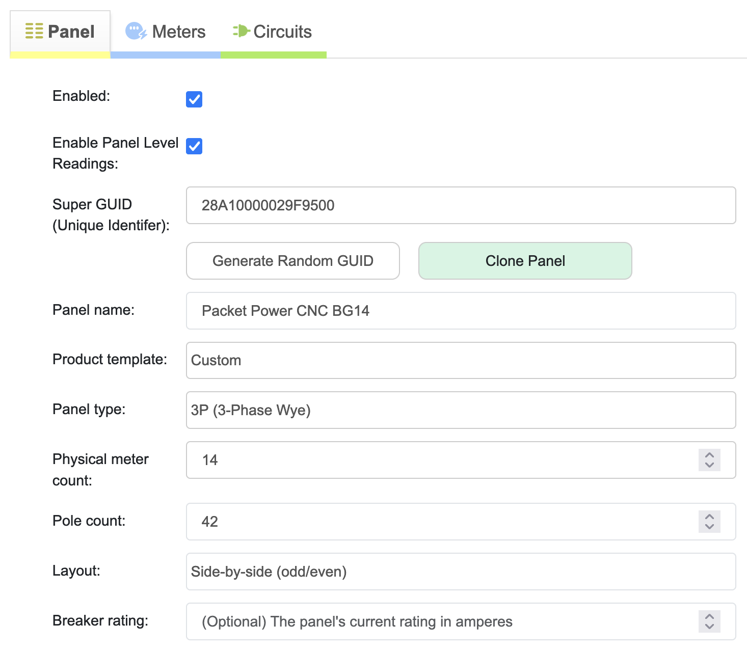
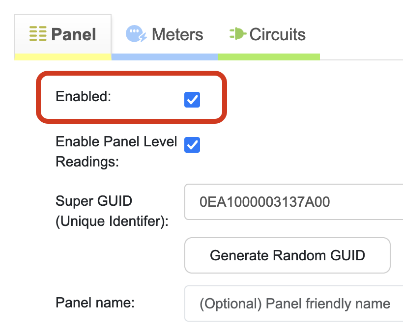
4. Select the Panel tab to edit the panel name or if instructed by Packet Power Support to edit other panel parameters including:
Super GUID (Unique Identifier): The unique 16-digit code assigned to the device (found on the actual device enclosure label); don't change this unless instructed by Packet Power Support
Panel name: User-defined descriptive name for the panel; edit as desired
Product template: Defines the general panel parameters based on product type; don't change this unless instructed by Packet Power Support
Panel type: The voltage service powering the panel; don't change this unless instructed by Packet Power Support
Physical meter count: The number of power meters in the overall monitoring device; don't change this
Pole count: The total number of breaker positions in the panel; don't change this unless instructed by Packet Power Support
Layout: How the circuit numbers are laid out in the panel; i.e. side-by-side (odd/even), side-by-side (sequential), or in-line; don't change this
Breaker rating: The panel's infeed current rating - an optional field that can be edited.
Below this information is a graphical depiction of the panel with information from the Panel, Meters and Circuits tabs.
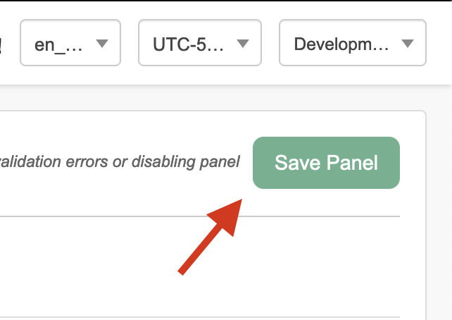
If any changes are made, click the green Save Panel button in the upper right corner of the screen.
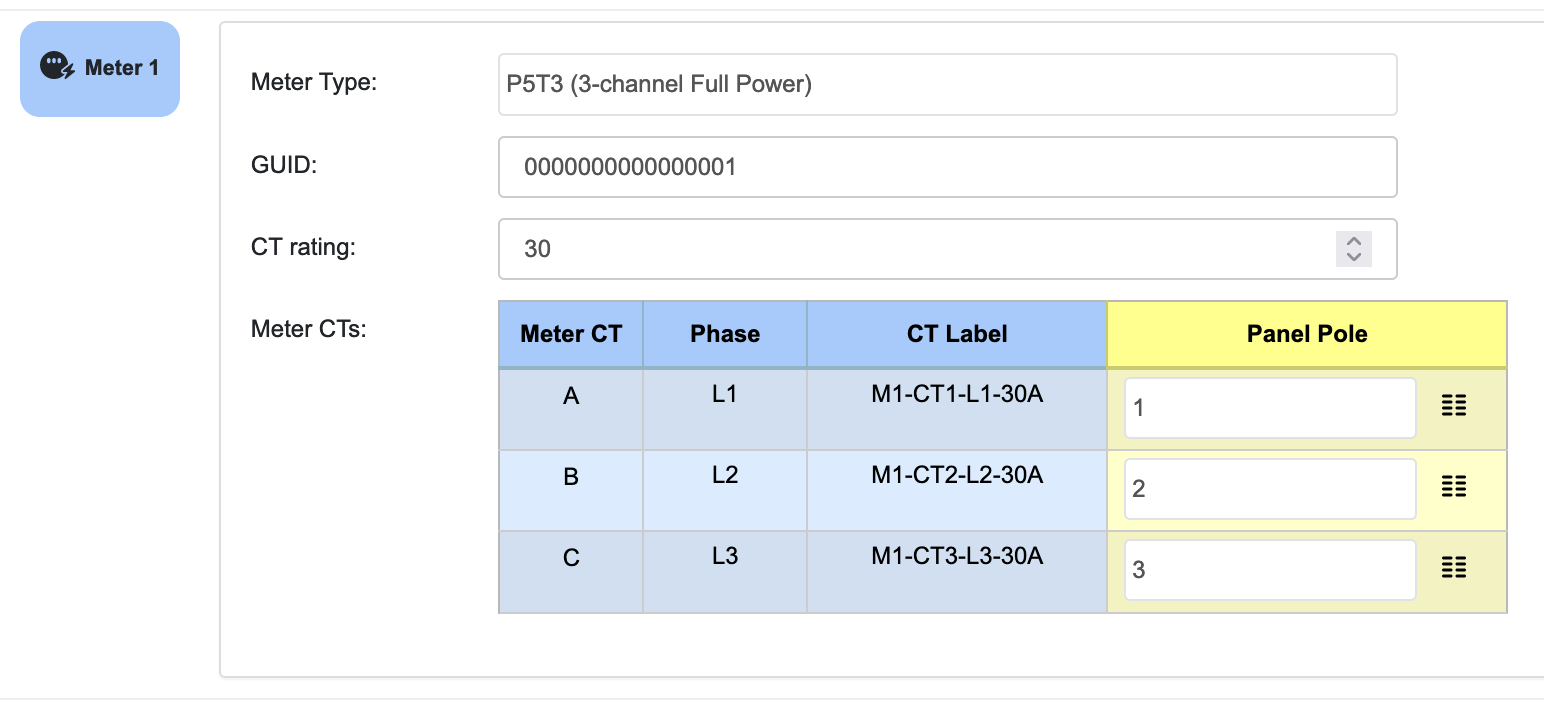
5. The Meters tab shows information about the physical meters in the monitoring device including the type of meter, its GUID, CT rating (if provided), and the CT label number(s) attached to each meter.
Do not edit any information on this tab unless instructed by Packet Power Support.
6. Select the Circuits tab to add information about individual panel circuits. You will be presented with a template to add information about each of the circuits in your panel.
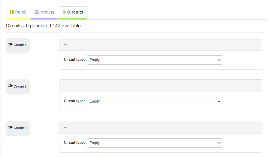
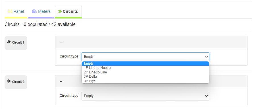
a. For each circuit, select the Circuit type from the drop down box.
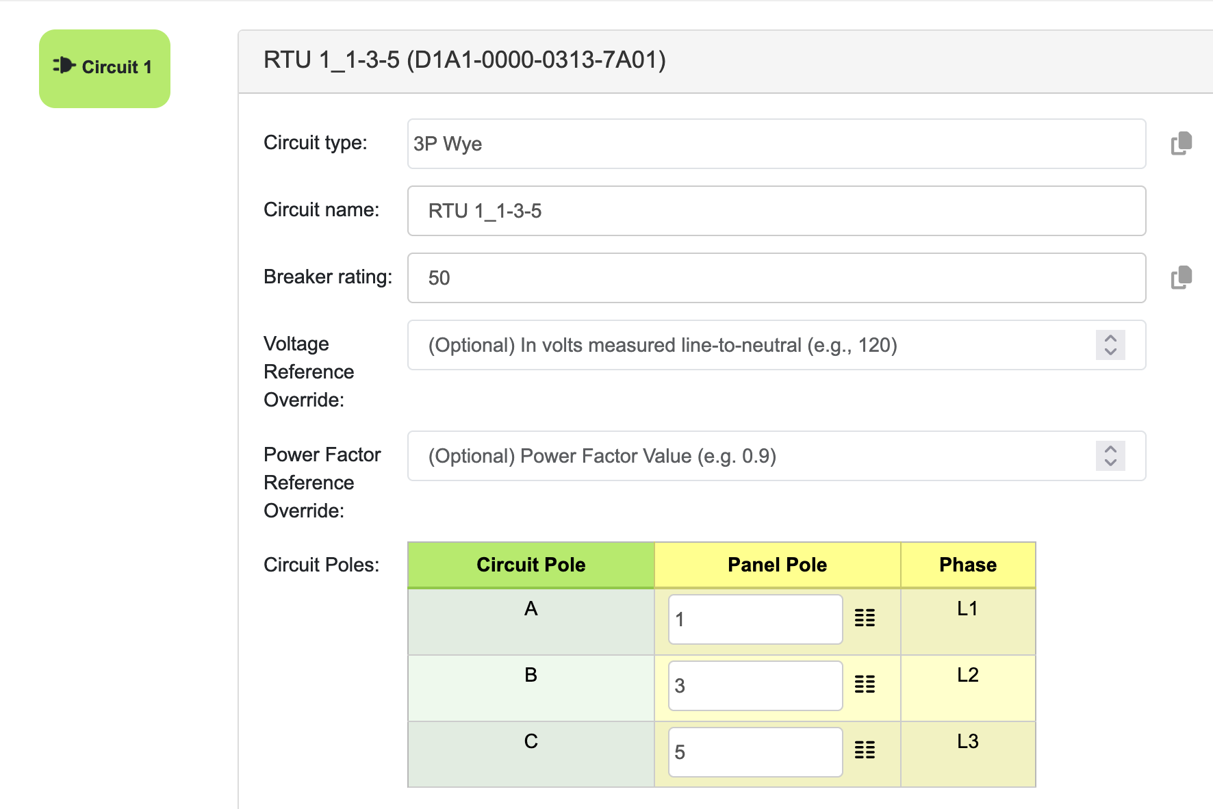
b. Complete the rest of the information for the first circuit.
Create a Circuit name that is meaningful to you. Hint: It can be helpful to include the breaker pole number(s) in the circuit name.
Provide Breaker rating (in amps)
Select the breaker numbers using the Panel Pole drop down box. Note that as you select Panel Pole numbers, they will not appear as a choice in the drop down menu again.
c. Complete these steps for each additional circuit.
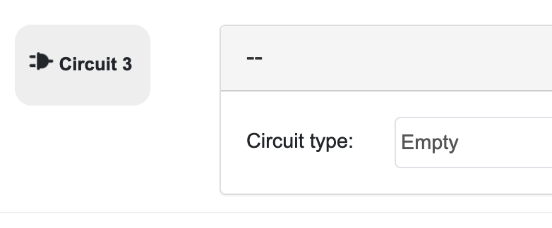
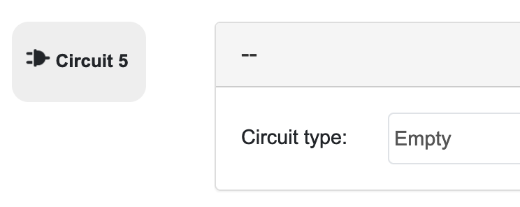
Note that the first circuit in our sample panel is a 3-phase circuit that uses poles 1, 3 and 5. As a result, we will leave the template for Circuits 3 and 5 empty.
6. Save changes to the panel by clicking the green Save Panel button at the top of the page. You must save changes before exiting the page to retain your edits. You may make additional edits after saving the panel.
Enable the panel map(s) in EMX
Go to the Panel tab in Virtual Panels. Click the Enabled radio button to enable the panel. A white checkmark in a green box indicates the panel is enabled.
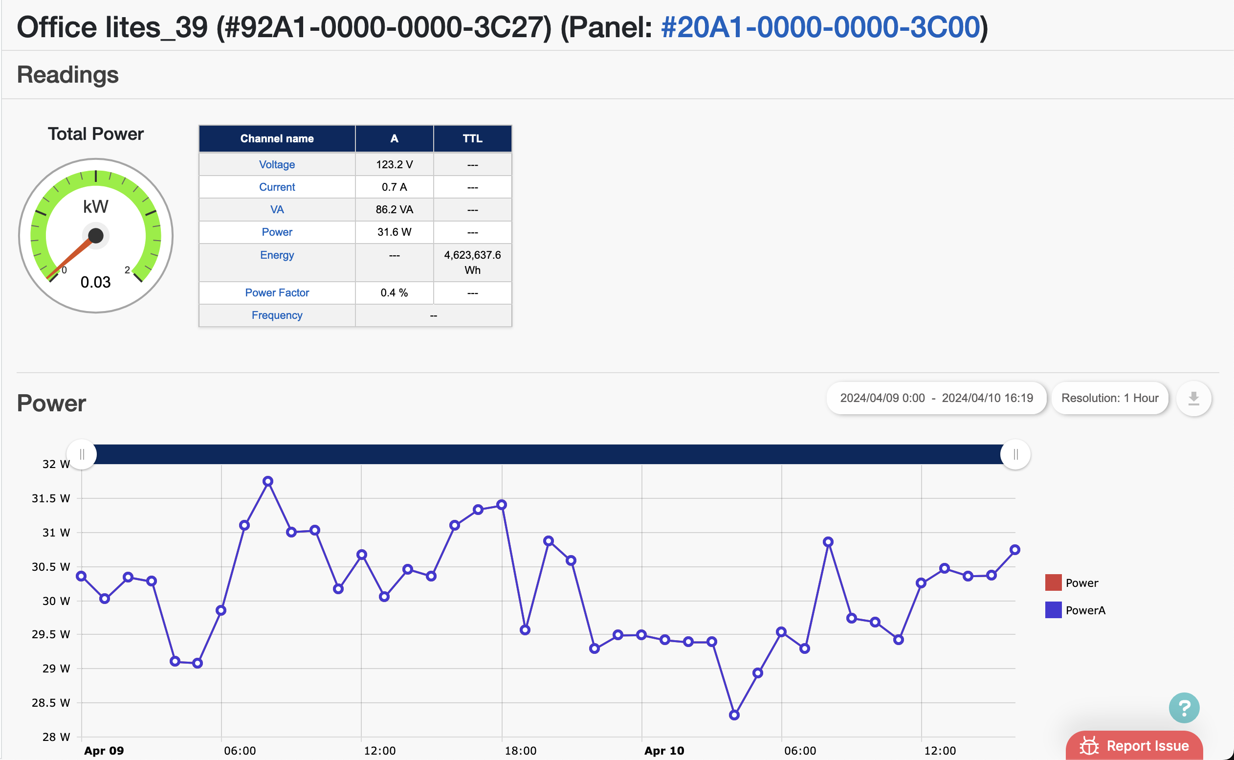
View the panel data in EMX
Once your panel is enabled and your device is live, you may view panel data in EMX.
Monitoring Device and Virtual Circuit GUIDs
Every Packet Power device has a unique 16-digit ID or GUID assigned.
-
Your BGXX monitoring device has a 16-digit GUID on a label attached to the device enclosure.
-
Virtual circuits are automatically assigned a 16-digit GUID when a panel is created. This virtual circuit ID appears in EMX.
-
Panel maps are unique by monitoring device and are assigned the same 16-digit ID as the device's GUID.
There is an association between device/panel ID and the virtual circuit IDs.
Device ID (same as Panel ID): 20A1-0000-0000-3C00
Virtual circuit ID: 3FA1-0000-0000-3C16
A1 will always be the 3rd and 4th digits of the 16-digit GUID for all panel device and virtual circuit IDs. This indicates the device is associated with a panel and that the virtual circuit is part of a panel.
The 7th through 14th digits will be the same for a device/panel ID as for the virtual circuits associated with that specific panel. These 8 digits will be unique to a specific panel and its corresponding virtual circuits.