

Supported Devices
IMD-02
-
PDUs with Geist Interchangeable Monitoring Device (IMD), variant IMD-02
-
5W5H6A9HXX-S
-
6HW56A9BXX-S-030160
-
8HW56A9BXX-S-030160
IMD-03
PDUs with Geist Interchangeable Monitoring Device (IMD), variant IMD-03
IMD-05
PDUs with Geist Interchangeable Monitoring Device (IMD), variant IMD-05
Required WNC Firmware
IMD-02
-
36.02 or newer
-
36.10 or newer for per-outlet readings (if supported by PDU)
IMD-03
-
36.10 or newer
IMD-05
-
36.42 or newer
Manufacturers Documentation
The following resources will be useful for the WNC configuration. Note, this is not a full guide to the interface on Geist PDUs.
Geist Upgradeable PDU Instruction Manual for IMD-03x
Required PDU Configuration
The device must be reset to factory defaults before connecting the WNC .
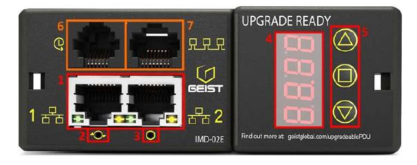
IMD-02 Devices
Insert a paper clip or other tool into the network-reset button (3 in the image below). Hold for 15 seconds to restore the default IP address.
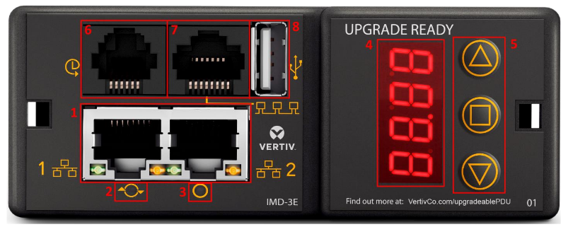
IMD-03 Devices
Insert a paper clip or other tool into the network-reset button (3 in the image below). Hold until the display shows "rESt" to restore the defaults.
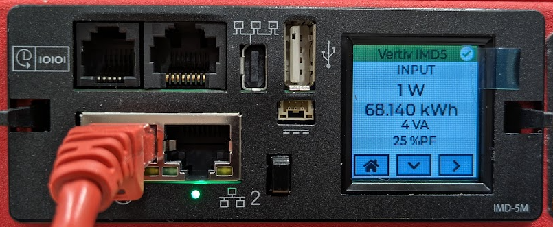
IMD-05 Devices
Use the touchscreen display to disable DHCP. The device should fall-back to a static IP address of 192.168.123.123.
WNC Connections
Connect one end of an Ethernet cable to the Ethernet port #1 on the PDU control panel
On the rear of the WNC, connect the other end of the Ethernet cable and the 5V DC power supply barrel plug.
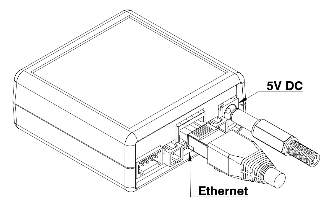
Optional: The WNC can instead be powered from the Geist PDU directly (certain models only). Contact sales@packetpower.com to discuss the necessary cabling.
Readings Reported
Not all readings are available for all Geist IMD-2/IMD-3/IMD-5 PDUs. For example, a single phase PDU will not report any readings for input phases B or C. Additionally, per-outlet readings are only available on a PDU that supports per-outlet readings.
|
Channel |
|
Voltage A |
|
Voltage B |
|
Voltage C |
|
Current A |
|
Current B |
|
Current C |
|
Power A |
|
Power B |
|
Power C |
|
Energy A |
|
Energy B |
|
Energy C |
|
Phase Angle A |
|
Phase Angle B |
|
Phase Angle C |
|
Total Power |
|
Total Energy |
|
Current X |