

The Wireless Network Connector (WNC) makes select metered devices that aren't currently networked work over Packet Power's wireless network. Plug the device into the Ethernet or serial port of a supported device. Configure the device to recognize the WNC then data will flow across the wireless network similar to other Packet Power wireless monitoring devices.
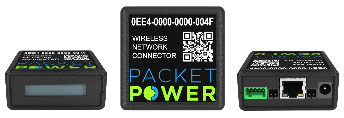
The WNC has an LCD to immediately verify correct operation. The device's connection end includes a green serial connector, two temperature probe ports on either side of an ethernet (RJ-45) connector, and a power connector.

Supported Devices
The Wireless Network Connector currently supports the following devices.
|
Manufacturer |
Device type |
Protocol |
Models |
WNCID |
WNC firmware version |
Configuration instructions |
|---|---|---|---|---|---|---|
|
APC |
Power strip |
SNMP |
AP78XX
|
5
|
Varies
|
|
|
Automatic Transfer Switch (ATS) |
SNMP |
AP77XX |
4 |
36.2 + |
||
|
Austin Hughes |
Power strip |
SNMP |
InfraPower with IP Dongle |
12 |
36.18 + |
|
|
BayTech |
Power strip |
SNMP |
MMP-10 |
21 |
36.40+ |
|
|
Geist
|
Power strip (PDU) |
SNMP |
Devices using:
|
|
|
|
|
Janitza |
Power meter |
Modbus RTU |
UMG 96RM |
13 |
36.20 + |
|
|
Liebert
|
Power strip |
SNMP |
MPH devices using:
|
11 |
|
|
|
RLE |
Multi-zone leak detection controller |
Modbus RTU |
LDRA6 |
10 |
36.12 + |
|
|
Sage |
Mass Flow Meter (gas, air, other fluid metering) |
Modbus RTU |
Paramount |
14 |
36.20 + |
|
|
Schneider |
Power meter |
Modbus RTU |
PM5XXX |
8 |
36.10 + |
|
|
Server Technology |
Power strip |
SNMP |
Supported PRO2 PDUs |
7 |
36.6 + |
|
|
Serial CLI |
Refer to table in ServerTech Serial Devices |
18 19 20 |
36.38+ |
|||
|
Veris |
Branch Circuit Monitors |
SNMP |
Veris H704
|
15
|
36.24 + |
|
|
nVent |
Power strip |
Modbus RTU |
enLOGIC PDUs |
17 |
36.24 + |
Support for other brands of power strips as well as standalone meters, UPSs, RPPs/PDUs, ATSs, Gensets and other devices will be added over time based on customer need. Contact info@packetpower.com to discuss.
Overall Installation and Configuration
These are the overall steps to install and configure a WNC for use with a supported device. Note that configuration details vary by device.
1. Ensure a Packet Power Gateway is installed
The WNC automatically connects to the wireless mesh network just like any other Packet Power monitoring device. A Packet Power Ethernet Gateway (version 4) is required to make the monitoring data available to your Building Management System or EMX Energy Portal.
2. Determine WNC mounting location
The WNC must be near the device it will monitor as the two will be connected with an Ethernet cable. It will also need a power source. The WNC comes with a 5V DC power supply with 1.5 meter cord length and works with most plug types including C13. Some power strips can power the WNC directly from USB or other ports. The WNC needs to be no more than 10-30 meters from the Packet Power Gateway or another wireless monitoring device, ideally line of sight. Avoid mounting near large metallic surfaces and never inside a fully enclosed metal structure. The rubber bumpers on the back of the included mounting bracket can be removed to expose 0.2" holes that can be used for permanent mounting with mechanical fasteners. The device may also be mounted via a DIN rail clip or with an optional magnet.
3. Configure the communications connection between the WNC and the monitored device
For information on establishing SNMP communication prior to WNC integration see: SNMP Communication from WNC to Target Device
Configuration settings differ by supported device type and firmware version. Click on the applicable Configuration instructions link in the table above for set up details by device type. Contact support@packetpower.com if additional information is needed.
4. Connect the monitored device and WNC by Ethernet cable, Modbus RTU cable, or Serial Adapter.
5. Connect power to the WNC if applicable.
Accessing Data
Once powered up, the WNC immediately sends monitoring data to the Ethernet Gateway. The Gateway makes the data accessible to Building Management Systems using standard protocols such as SNMP, Modbus and Ethernet/IP. The data is also accessible via EMX Energy Portal for EMX subscribers.