

Supported Devices
-
Janitza Power Meter UMG 96RM and 96RM-E
-
Possibly other Janitza Power Meter models with Modbus RTU support
Required WNC Firmware
36.20 or newer
As a Modbus RTU device, the WNC must be pre-configured to connect to this third-party device. Please contact support@packetpower.com to discuss configuration options.
Janitza documentation
The following resources will be useful for the WNC configuration. Note, this is not a full guide to the management interface on Schneider devices.
Janitza UMG 96RM-E Product Page
Janitza UMG 96RM-E Installation Manual (second half is English)
Janitza UMG 96RM-E User Manual
Required meter configuration
The device must have its Modbus RTU settings correctly set before connecting the WNC. The desired Modbus RTU settings are
-
baud rate: 115200,
-
data bits: 8,
-
parity: none,
-
device address: 1.
These are the factory default settings, so it is unlikely that you will need to change these settings unless you have previously reconfigured the meters to work with a different system. These settings cannot be changed via the LCD + buttons interface, and can only be changed via Modbus RTU communications. If your meter needs to have these settings change, please follow the instructions in the meter user guide to update registers 0001 (device address) and 0002 (baud rate).update registers 0001 (device address) and 0002 (baud rate).
If your meter is already configured for alternative address, baud rate, or parity, please contact support@packetpower.com to discuss factory-configuration options.
WNC Connections
The WNC support for Modbus RTU is capable of half- or full-duplex operation. That is, it provides separate connections to the WNC RS-485 transmitter and receiver signal pairs. For a half-duplex RS-485 bus, these pairs are connected together and connected to two-conductor twisted-pair wiring. For a full-duplex RS-485 bus, these pairs are kept separate and connected to four-conductor twisted-par wiring. Typically, half-duplex is used for industrial control systems like these.
The WNC hardware contains the necessary terminating resistors, as well as a ground connection for any cable shielding, if used. Please contact support@packetpower.com in case of questions regarding proper wiring of the Modbus RTU RS-485 bus.
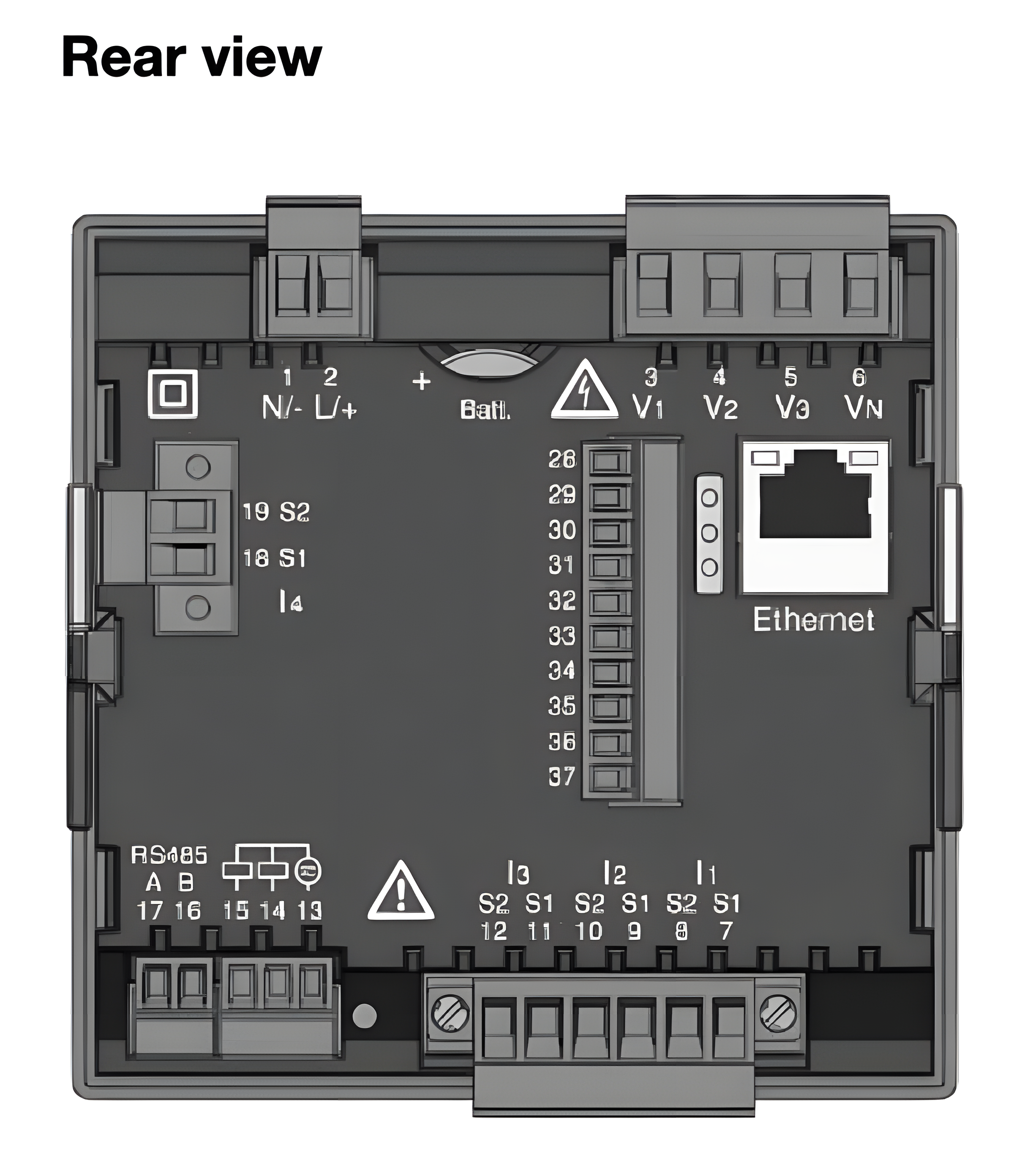
Connect the Modbus RTU twisted-pair cable to the power meter using the screw terminals. Janitza terminals are typically labeled "A" on one connection, and "B" on the other connection.
Janitza defines A and B different from most vendors.
|
A = inverted signal |
B = non-inverted signal |
|---|---|
|
A = “-" |
B = "+" |
|
A = T x D - / R x D |
B = T x D + / R x D |
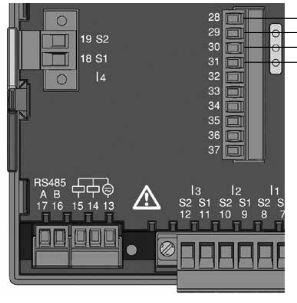
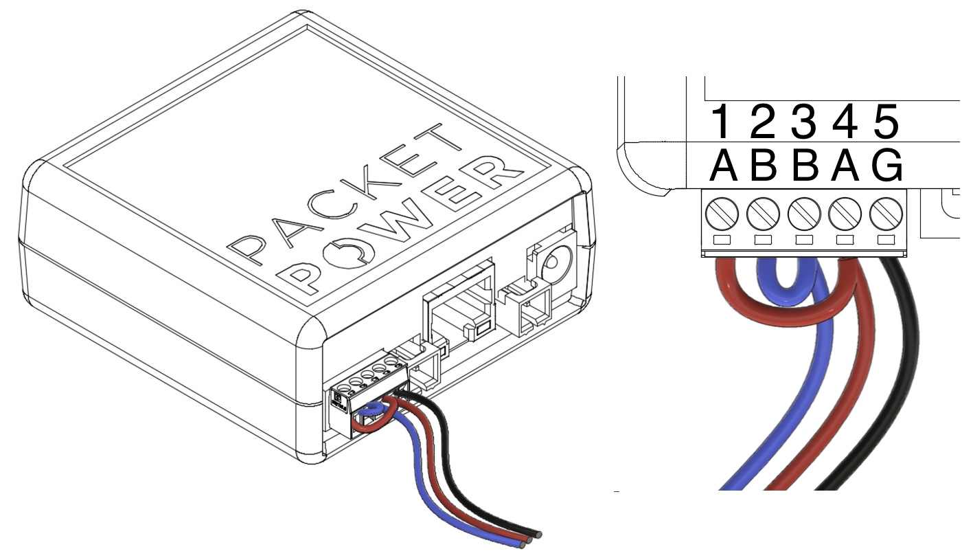
On the rear of the WNC, use the green 5-pin plug to connect the Modbus RTU twisted-pair cable. Connect pins 1 and 4 together to the "A" wire in the cable. Connect pins 2 and 3 together to the "B" wire in the cable. If the cable has a shield, connect it to ground at ONLY ONE point in the modbus network. Since the WNC will act as a Modbus RTU master, pin 5 can be used to ground the cable shield.
Readings Reported
|
Modbus RTU Register Number |
Channel |
Description |
|---|---|---|
|
19000 |
Voltage A |
L1-N voltage |
|
19002 |
Voltage B |
L2-N voltage |
|
19004 |
Voltage C |
L3-N voltage |
|
19012 |
Current A |
Current 1 |
|
19014 |
Current B |
Current 2 |
|
19016 |
Current C |
Current 3 |
|
19018 |
Current N |
Current N |
|
19020 |
Power A |
Power 1 |
|
19022 |
Power B |
Power 2 |
|
19024 |
Power C |
Power 3 |
|
19026 |
Power |
Total Power |
|
19070 |
Energy A |
Energy 1 |
|
19072 |
Energy B |
Energy 2 |
|
19074 |
Energy C |
Energy 3 |
|
19076 |
Energy |
Total Energy |
|
19050 |
Line Frequency |
Frequency (typically 50 or 60 Hz) |
|
19044 |
Phase Angle A Power Factor A |
Phase A voltage-current angle Phase A power factor |
|
19046 |
Phase Angle B Power Factor B |
Phase B voltage-current angle Phase B power factor |
|
19048 |
Phase Angle C Power Factor C |
Phase C voltage-current angle Phase B power factor |
|
19110 |
THDv A |
Phase A Voltage Total Harmonic Distortion (%) |
|
19112 |
THDv B |
Phase B Voltage Total Harmonic Distortion (%) |
|
19114 |
THDv C |
Phase C Voltage Total Harmonic Distortion (%) |
|
19116 |
THDi A |
Phase A Current Total Harmonic Distortion (%) |
|
19118 |
THDi B |
Phase B Current Total Harmonic Distortion (%) |