

Packet Power has different power meter families with different displays:
-
MP277, BGPXX, BGSXX, plus RGXX and SGXX cables shipped September 2021 or later
-
MP480-3MV, PGxxx, MGxxx, BGXX, BGSXXH, plus RGXX and SGXX cables shipped before September 2021
-
Current-only MC240, CGxx and BGxx, BGPxx, BGSxx monitors with at least one round current-only meter
MP277, BGPXX and BGSXX monitors plus RGXX and SGXX cables shipped September 2021 or later
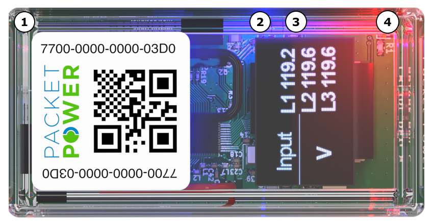
The P5T8 power meter features a high-quality graphical display that presents various information including device configuration, device status and electrical readings.
Status lights
|
|
1 🟩 Green Light (Power Status)
|
|
2 🟦 Blue Light (Mesh Status)
|
|
3 🟥 Red Light (Non Mesh Status)
|
|
4 🟧 Amber Light (Power Status)
|
Graphical display
The P5T8 power meter graphical display shows device configuration and electrical readings. This information is collected into a series of pages, displayed in sequence with a configurable period of off-time between each displayed page. Tapping the side of the display advances to the next page in the sequence, temporarily overriding the normal page rotation timing. After 10 seconds, with no further tap, the auto-sequence resumes.
There are a few different display sequences that can be selected, based on the desired information to be displayed, using the tap interface. These sequences are detailed in the following table.
|
Startup sequence |
The Packet Power logo and name are displayed when the device first powers up, followed by a sequence of power on self-test (POST) display pages. |
|---|---|
|
Boot sequence |
The boot sequence is displayed once at startup (following the logo), but is not normally shown as part of any display sequence. However, if the page is manually advanced by a button tap from the user, the boot sequence pages will be displayed after the end of the normal page sequence. Firmware and checksum Version number consists of two parts: image.version (35.X) Checksum is a sequence of 8 hexadecimal digits (0-9, A-F) System and meter status For both the system and metrology subsystem, displays either "OK" or an error code |
|
Display sequence: Standard |
The standard display sequence provides input-level readings for the configured input lines (L1, L2, and/or L3). Input voltage [V] Input current [A] Input power [W] Input energy [Wh] Input energy, total [Wh] |
|
Display sequence: Full |
The full display sequence provides input-level readings for the configured input lines (L1, L2, and/or L3) as well as the infrared output pulse count, and details of the load-side circuits. Input voltage [V] Input current [A] Input power [W] Input energy [Wh] Input energy, total [Wh] Pulses - the count of the IR output pulses Load details One page per load circuit depending on meter configuration May show current [A], power [W], and/or energy [Wh], depending on meter configuration |
|
Display sequence: Blank |
This sequence does not display any information, to be used if the user desires a completely blank display. A button tap will still be able to display the Boot Sequence pages when desired. |
MP480-3MV, PGxxx, MGxxx, BGXX and BGSXXH monitors plus RGXX and SGXX cables shipped before September 2021
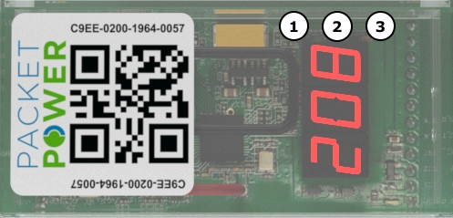
The P5T3 and P5T3X-generation power meters have 3 large alpha-numeric LEDs that provide local display of monitoring data and 3 small lights adjacent to the LEDs that provide operating status information.
Status lights
|
|
1 🟩 Top Green Light
|
|
2 🟥 Red Light
|
|
3 🟩 Bottom Green Light
|
Numerical display
The P5T3 and P5T3X meters can be configured to display all or some of the following data via the numeric LEDs. The order of display can also be customized. The data type indicator is shown followed by the corresponding value, e.g. to show a reading of 10.1 amps on channel A, the PMM displays "A1" followed by "10.1".
|
Power on sequence |
P5= XXX firmware version |
|---|---|
|
Normal operation |
Cycles through repeatedly
Id = ABC last 3 digits of the node ID A1 = ### current on channel A [A] U1 = ### voltage on channel A [V] A2 = ### current on channel B [A] U2 = ### voltage on channel B [V] A3 = ### current on channel C [A] U3 = ### voltage on channel C [V] |
|
Available but not enabled in standard configuration |
P1 = ### power on channel A [kW] F1 = ### power factor on channel A [n] P2 = ### power on channel B [kW] F2 = ### power factor on channel B [n] P3 = ### power on channel C [kW] F3 = ### power factor on channel C [n] Fr = ### frequency [Hz] |
Current-only MC240, BGxx, BGPxx, BGSxx monitors with at least one round current-only meter
The P5J6 round current-only meter has four large alpha-numeric LEDs that provide local display of monitoring data. It can be configured to display some or all of the following data. The order of display can also be customized.
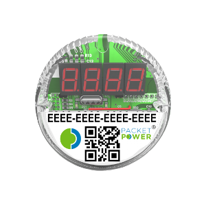
The data type indicator is shown followed by the corresponding value. For example: To show a reading of 10.1 amps on channel A, the meter displays A1 followed by 10.1.
-
P5 = XXX firmware version
-
Id = ABC (last 3 digits of the meter node ID)
-
C1 ... C6 = Current on channel 1-6 in amps
-
A1 ... A6 = Current utilization hours on channel 1-6 in amp hours
-
T = Internal temperature in °C