

Supported Devices
-
C2SG36TE-4PAE2M66
-
Other ServerTech PRO1 or PRO2 PDUs may also work, especially three-phase PDUs
Required WNC Firmware
-
36.8 or newer
-
Per-outlet readings (if supported by the PDU) included in WNC firmware version 36.10 or newer
ServerTech documentation
This site is not intended to provide a full guide to the management interface on ServerTech devices. The following resources will be useful for the WNC configuration.
Required PDU configuration
-
The device must be configured before connecting the WNC.
-
This is accomplished via the web console or the serial console. please follow the instructions in the PDU user guide.
-
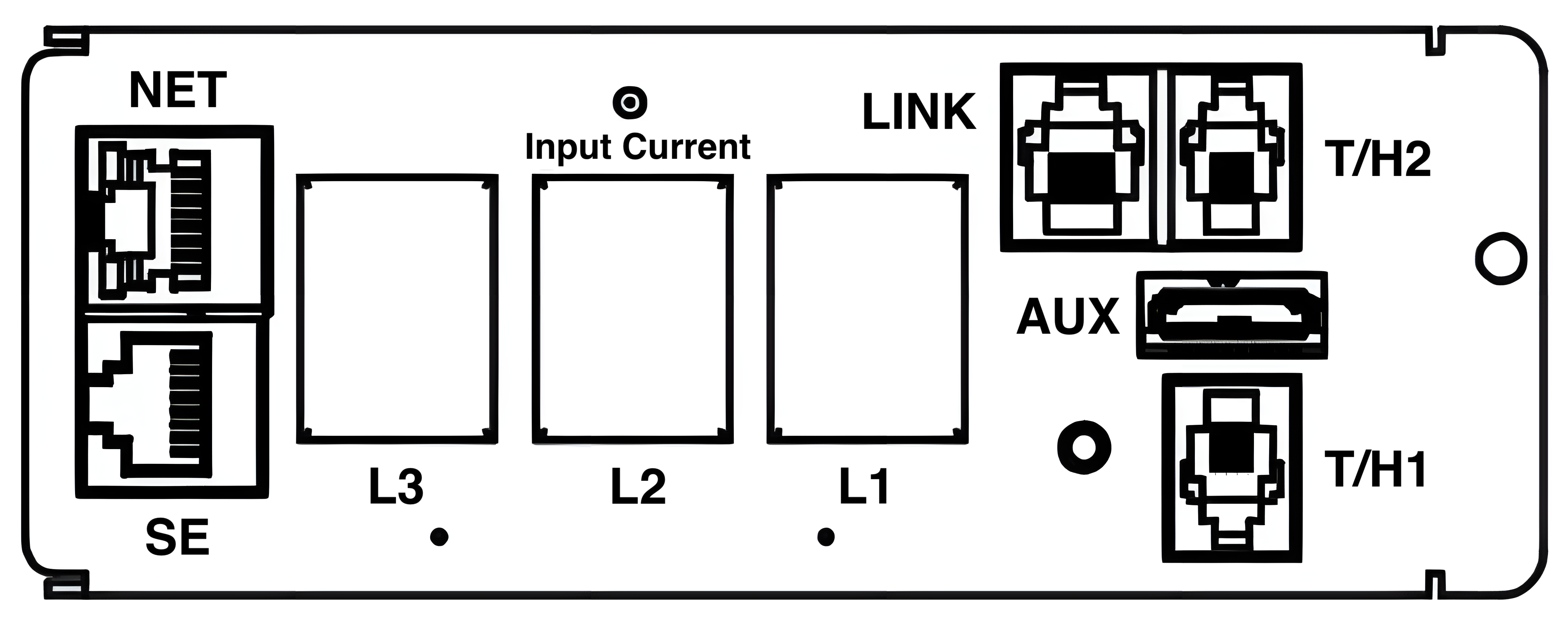
Alternatively, a factory reset can be performed by using the reset button inside an unlabeled hole next to the LED displays or network port. Use a paperclip or other tool to press and hold the button for between 10 and 15 seconds. The reset process will take about 3-1/2 minutes to complete. This process will not affect outlet on/off status. Please refer to the ServerTech FAQ documentation for more details.
-
-
If the device cannot be factory reset, then the device must be configured with static IP networking settings for the ethernet port.
IP address: 192.168.1.254
Subnet Mask: 255.255.255.0
Default gateway: 192.168.1.1
This can be accomplished in a few ways.
-
If the device is currently connected to and accessible via an existing IP network, follow the instructions in the user manual.
-
If the device is not already connected to an IP network, follow the instructions in the manufacturer's installation guide, quick start guide, or user manual to configure the device with a static IP address. Options here may include local serial console connection.
WNC Connections
1. Connect one end of an ethernet cable to the NET port on the PDU control panel.
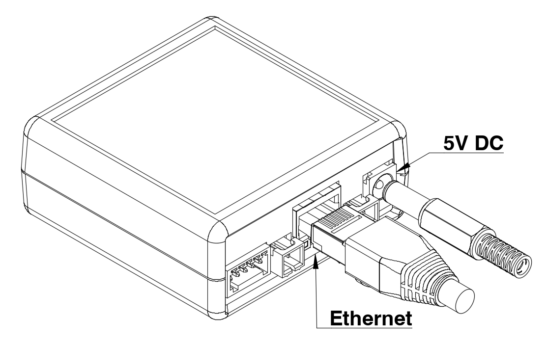
2. On the rear of the WNC, connect the other end of the Ethernet cable and the 5V DC power supply barrel plug.
SNMP Readings Reported
|
SNMP OID |
Channel |
Description |
|---|---|---|
|
1.3.6.1.4.1.1718.4.1.3.3.1.3.1.1 |
Total Power |
PDU total power |
|
1.3.6.1.4.1.1718.4.1.3.3.1.10.1.1 |
Total Energy |
PDU total accumulated energy |
|
1.3.6.1.4.1.1718.4.1.5.3.1.6.1.1.1 |
Current A |
PDU phase A current |
|
1.3.6.1.4.1.1718.4.1.5.3.1.6.1.1.2 |
Current B |
PDU phase B current |
|
1.3.6.1.4.1.1718.4.1.5.3.1.6.1.1.3 |
Current C |
PDU phase C current |
|
1.3.6.1.4.1.1718.4.1.5.3.1.3.1.1.1 |
Voltage A |
PDU phase A voltage |
|
1.3.6.1.4.1.1718.4.1.5.3.1.3.1.1.2 |
Voltage B |
PDU phase B voltage |
|
1.3.6.1.4.1.1718.4.1.5.3.1.3.1.1.3 |
Voltage C |
PDU phase C voltage |
|
1.3.6.1.4.1.1718.4.1.5.3.1.9.1.1.1 |
Power A |
PDU phase A power |
|
1.3.6.1.4.1.1718.4.1.5.3.1.9.1.1.2 |
Power B |
PDU phase B power |
|
1.3.6.1.4.1.1718.4.1.5.3.1.9.1.1.3 |
Power C |
PDU phase C power |
|
1.3.6.1.4.1.1718.4.1.5.3.1.10.1.1.1 |
Phase Angle A |
PDU phase A voltage-current angle |
|
(derived from reading above) |
Power Factor A |
PDU phase A power factor |
|
1.3.6.1.4.1.1718.4.1.5.3.1.10.1.1.2 |
Phase Angle B |
PDU phase B voltage-current angle |
|
(derived from reading above) |
Power Factor B |
PDU phase B power factor |
|
1.3.6.1.4.1.1718.4.1.5.3.1.10.1.1.3 |
Phase Angle C |
PDU phase C voltage-current angle |
|
(derived from reading above) |
Power Factor C |
PDU phase C power factor |
|
1.3.6.1.4.1.1718.4.1.5.3.1.13.1.1.1 |
Energy A |
PDU phase A accumulated energy |
|
1.3.6.1.4.1.1718.4.1.5.3.1.13.1.1.2 |
Energy B |
PDU phase B accumulated energy |
|
1.3.6.1.4.1.1718.4.1.5.3.1.13.1.1.3 |
Energy C |
PDU phase C accumulated energy |
|
1.3.6.1.4.1.1718.4.1.3.3.1.11.1.1 |
Frequency |
AC line frequency (likely 50 or 60 Hz) |
|
1.3.6.1.4.1.1718.4.1.8.3.1.3.1.1.X |
Current X |
PDU outlet X current |
|
1.3.6.1.4.1.1718.4.1.8.3.1.9.1.1.X |
Power X |
PDU outlet X power |