

These monitors have a solid core current transducer (CT) permanently attached to them, and the whole assembly is mounted on the conductor. Some of the steps are common to the procedure to install with external CTs.
Prepare mounting location for the monitor(s)
Several mounting options are available – typically mechanical (screws, cable ties, or the like), DIN rail, or an optional panel on which multiple meters can be mounted. Take care to locate the monitors where wireless radio communication is possible (not fully enclosed in metal, etc.).

Install the Monitor with Integrated CT on the circuit
Since the CT is solid core, it is necessary to disconnect the conductor to slide the CT/monitoring unit over it. It is critical to orient the direction of the current transducer correctly in relation to the conductor to avoid getting negative power readings. Always install with the arrow on the CT pointing as indicated in the illustration below. The blue arrow box represents the actual monitor with integrated CT and its arrow direction. Reconnect the conductor when complete.

Install the Voltage Source Lead
The Voltage Source Lead is designed to bring power from the DC circuit to the monitor. The monitor will also use these voltage values to calculate power and energy. Over current protection such as a breaker or fuse should be use (fusing can be purchased from Packet Power if needed).
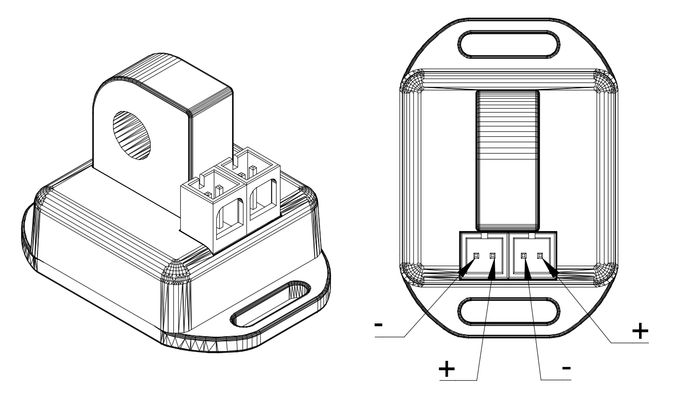
Take care to observe correct polarity.
-
Connect the bare wire ends of the lead to the bus and insert the two-pin connector into either of the two matching voltage connectors on each monitor. A Voltage Jumper can be used to share power with other monitors that are monitoring circuits on the same panel.
-
Connect one end of the jumper to the monitor with the voltage lead and the other end to the next monitor. You can then connect additional monitors using jumpers if you would like.
-
Once the unit has access to power, a small yellow light should begin to flash and then turn solid when the unit makes a radio connection.