

Installation Process Overview
-
Install the Ethernet Gateway(s) on your IP network.
-
Verify that each monitoring units is on the same radio zone as the gateway(s)
-
Install the monitors.
-
Verify that the monitors are communicating with the gateway.
-
Verify that the monitors are reading the correct voltage and amperage.
-
If you are using the EMX portal, verify it is receiving readings from the gateway.
-
If not using EMX, configure the Gateway to enable Modbus or SNMP polling from your monitoring application.
Step 1: Install Ethernet Gateways
Use the Gateway Quick Start guide to see how to add the correct network settings for your network.
See: Wireless Gateways for more information.
Verify the Gateway’s radio zone is what you expected and update it if necessary.
Step 2: Verify DC Monitor Radio Zones
Each DC Monitor will have a label identifying the wireless radio zone it is set to. This radio zone must match the one configured on the Ethernet Gateway(s).
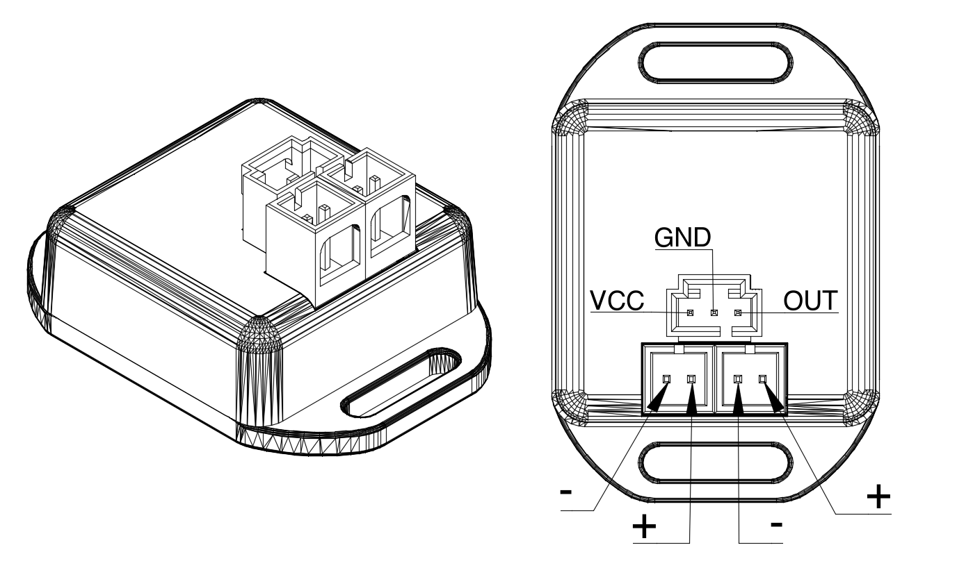
Step 3: Install the DC Monitors and CTs
Note: Monitors’ power leads are color coded as RED (positive) and BLACK (negative). This may differ from the standard in your facility – be sure to connect red (+) to your (+) and black (-) to your (-) even though the colors may not match.
There are three variations to Step 3, each with its own process. Follow any of these links to open up the procedure for that version:
Step 4: Verify Communication with a Gateway
Logon to the Gateway’s console with a browser on the same network using a URL of the form http://gateway_ip_address. Under Monitoring Data in the menu, select Power Nodes and look for the GUID of the DC Monitor to see if the monitor has connected to the gateway. (See Monitor Identification in the Appendix for how to identify that ID.)
Step 5: Verify Correct Voltages and Current Are Being Read
If step 4 is successful, click on the “readings” icon and verify that the voltage and amperage readings appear to be correct. If current is reading negative and you are using a CT, the CT should be turned to face the opposite way on the conductor. If current is zero and you are using a shunt adapter, check the polarity of the shunt.
Step 6: Verify EMX is Receiving Readings from Gateway(s)
If you have chosen to have your gateway(s) report to EMX, log in to EMX and on your account’s dashboard, look under Gateway Activity to see if the list includes the gateway(s) you are using for this purpose. You can then click on the gateway to check the list of nodes reporting to this gateway. You should be able to find the GUID(s) of your DC Monitor(s). Clicking on the monitor’s GUID should take you to that monitor’s detailed readings page.
Step 7: Configure Your Application to Poll Gateway(s)
If you have chosen to collect the monitoring data from a third party application rather than EMX, refer to the Gateway documentation for details on how to access data using SNMP or Modbus. A summary and links to references are included here.