

System Overview
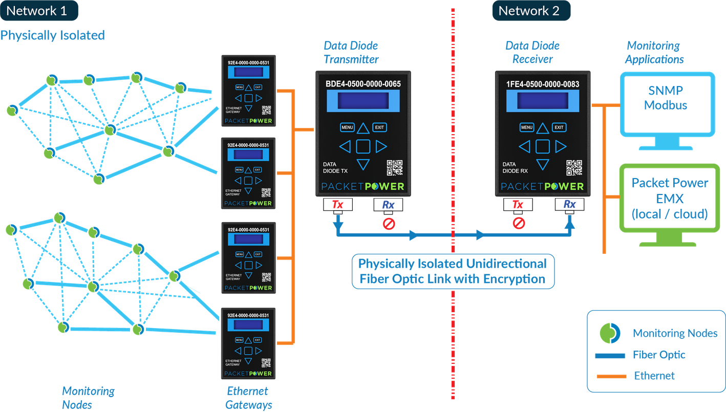
Packet Power’s Data Diode allows a one-way secure transfer of monitoring data between two isolated IP networks via a unidirectional encrypted fiber optical link. The single direction of the optical link is hardware-based. It is physically impossible for the link to operate in the other direction regardless of any software operating on either end of the link.
The system collects data from up to six Gateways operating inside an isolated network and aggregates that data in the Data Diode Transmitter. The Transmitter utilizes a fiber optical link to broadcast data to the Data Diode Receiver. The Transmitter has a single outgoing / transmission fiber link on it's transceiver which is linked to the Data Diode Receiver's receiver port. The transmit cable on the Data Diode Receiver is removed disabling any traffic from flowing into the segregated network. The user can then safely acquire data from the outside network without the need to interface with the isolated network. The data provided is the same data that is sent from standard Packet Power Gateways (Modbus TCP/IP, SNMP or EMX cloud data).
System Physical Installation
-
The Data Diode Transmitter and Receiver pair must be installed within 3m of each other using the fiber optical link provided. Fiber optic cable may be cut to size using proper shearing tools or ordered up to a 3m length. Do not bend or fold the cable.
-
The Transmitter and Receiver pair must have the Fiber Optic Converters plugged into the respective USB ports of each device. The converters are agnostic and can be exchanged between the Transmitter and Receiver devices.
-
The fiber optic cable for the Transmitter must always be in the "Tx" port of the fiber optic port.
-
The fiber optic cable for the Receiver must always be in the "Rx" port of the fiber optic port.
-
The converters are powered directly from the USB power supplies.
-
The transmitter and receiver each require a 5 VDC power source which can be provided by the universal power supply provided or may use any 5VDC source from a USB power supply or 5 VDC PoE splitter.
-
The Data Diode Transmitter shall be connected to the inside or isolated network; it is critical that this is the same network that any of the up to six Gateways are connected to.
-
The Data Diode Receiver shall be connected to the outside or exposed network; it is critical that this exposed network does not have any connectivity to the isolated network in order for the system to effectively isolated.

Configuring the Transmitter
The Data Diode function is a licensed feature of the EG4 Gateway. Both the Receiver and Transmitter need to have the associated license and Data Diode function enabled.
-
To confirm that the Data Diode license is in enabled go to the Gateway console by entering the IP address of the Gateway / Data Diode Tx (Transmitter). For more information on configuring the IP address of the Gateways clickhere.
-
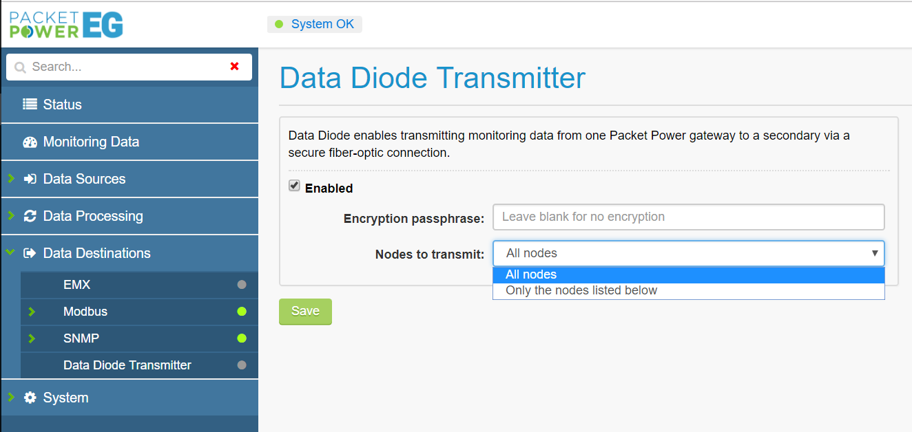
Under the left hand menu of the Gateway Console select [Data Destinations] then [Data Diode Transmitter]
-
Make sure that the "Enabled" check box is selected. This should make the green dot next to the "Data Diode Transmitter" appear on the left hand menu under that [Data Destinations] tab.
-
Enter an encryption passphrase if data encryption is desired.
-
Select the nodes (monitors) that the Data Diode will transmit data from using the "Nodes to transmit" drop down menu. Selecting "All nodes" will broadcast data from all nodes associated with the Transmitter. Selecting "Only the nodes listed below" will allow a partial selection of associated nodes to pass through the network.
-
Note that the Data Diode Transmitter can broadcast data from up to six associated Gateways that are on the same network as the Transmitter. The associated Gateways must be "peered" with the transmitter. For details about peering associated Gateways click here.
Configuring the Receiver
The Data Diode Receiver is pre-configured with the exception of the network details such as IP address. To configure the network specifications of the Receiver (Rx) module follow the details here.