

Remote CTs are available in a wide variety of form factors and current ratings. Consult Packet Power for a full listing of available remote current transducers.
.png?cb=8071e98d1d39948089e6bed84759d45d)
Prepare mounting location for the monitor(s)
Several mounting options are available – typically mechanical (screws, cable ties, or the like), DIN rail, or an optional panel on which multiple meters can be mounted. Take care to locate the monitors where wireless radio communication is possible (not fully enclosed in metal, etc.).

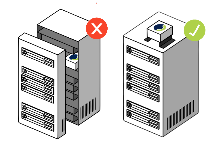
Install CTs with Correct Orientation
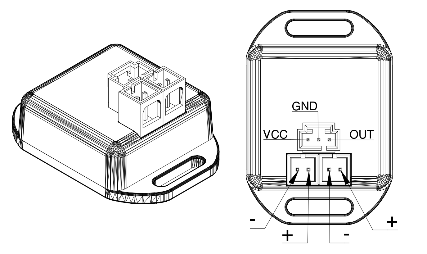
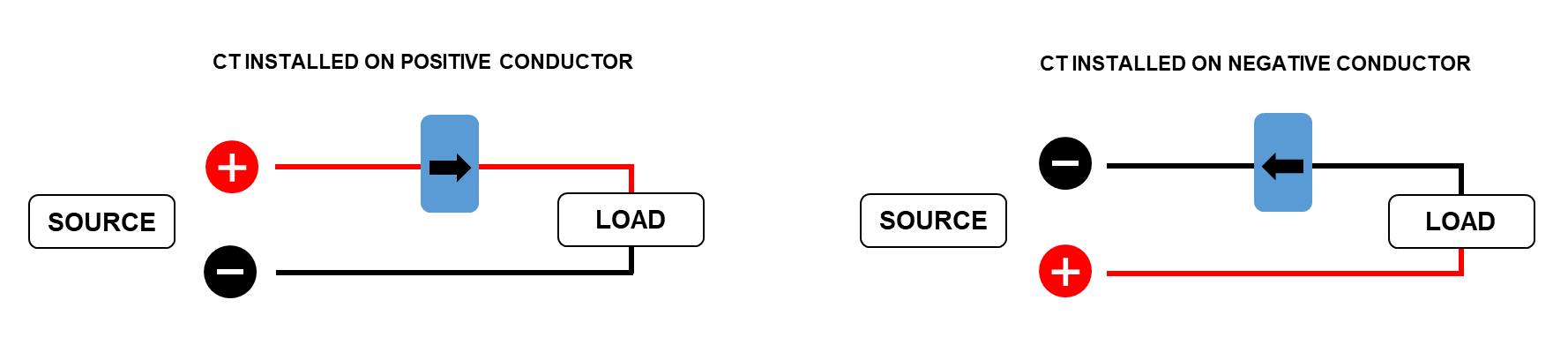
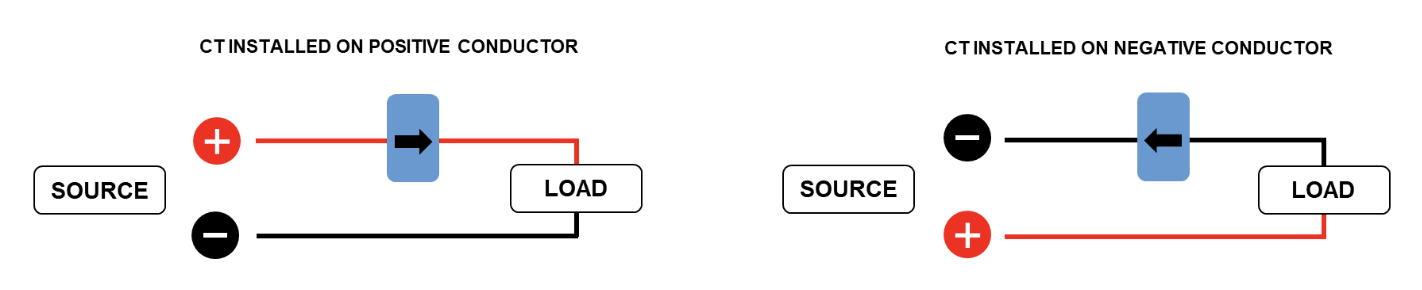
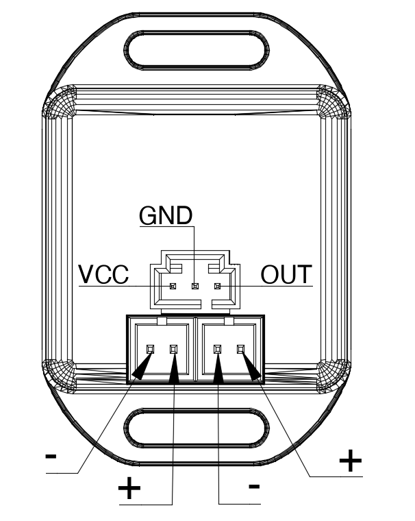
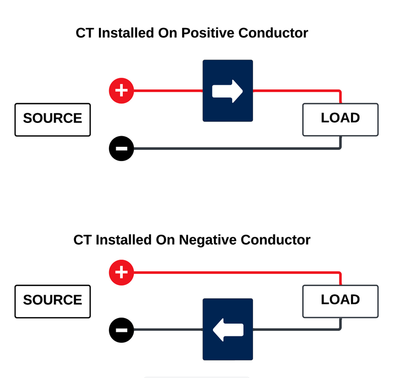
For each monitor, connect the CT lead to the monitor using the black three-pin connector and to the CT using the green connector (smaller CTs may be hardwired to the lead). Ensure the CT is the right one for the monitoring unit as using the wrong CT could result in incorrect readings. Install the current transducer on the circuit to be monitored. It is critical to orient the CT correctly in relation to the conductor to avoid getting negative power readings. Use the illustration below for correct orientation where the blue box with arrow reflects the arrow direction on the actual CT.

Note: Split core CTs will use either a small screw or a clasp to hold the top and bottom halves together. Use care as these parts can break and be sure to refasten the unit correctly.
More detail on individual CTs can be found below.
Documents are externally available here.