

Branch circuit and multi-circuit monitors (Packet Power BGXX devices) report data to Ethernet Gateways. Panel maps translate the readings into "virtual circuits" that match the the circuit mix in your panels. The maps can be customized with circuit names that make sense to you. Monitoring data can be viewed at an individual circuit level or as a panel. See Device and Circuit GUIDs at the bottom of this page for more information about Packet Power 16-digit IDs.
If you ordered a panel map with your BGXX device and do NOT subscribe to EMX, follow these steps to customize the map and view the data. If you are an EMX subscriber, go to EMX Panel Editor for the steps to customize the map.
Set Up Peer Gateways
If you have multiple BGXX devices reporting into multiple Ethernet Gateways, associate the gateways into a master/peer relationship. Store the panel maps on the master gateway. This lets you get all readings from all the panels from one source as well as provides a repository for all the panel maps.
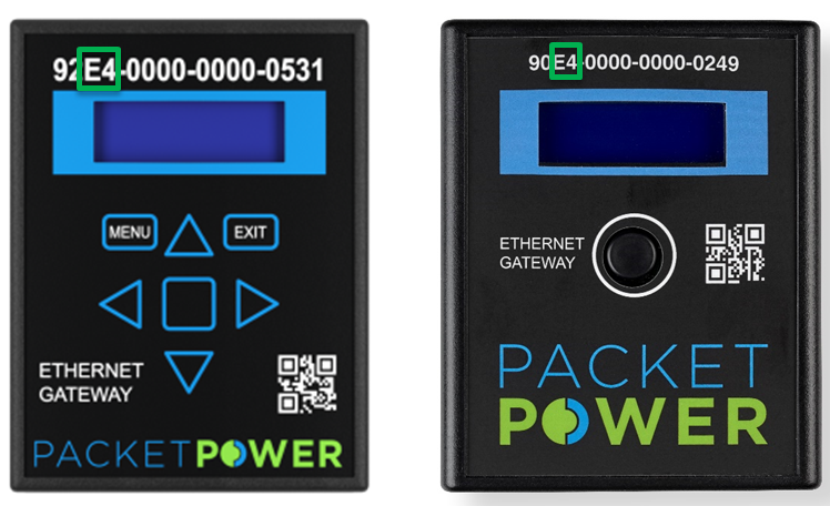
1. Select a Version 4 gateway to be the master. Version 3 gateways cannot serve as master gateways but they can be peer gateways. All Version 4 Gateways have "E4" as the third and fourth digits in their 16-digit GUID.
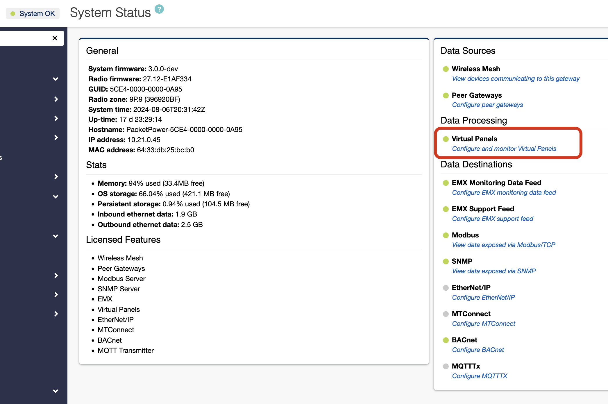
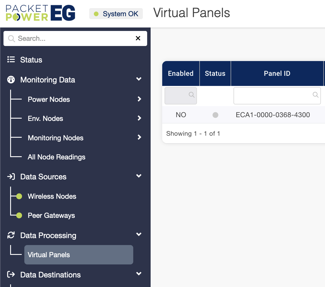
2. Confirm that the master gateway is enabled for panel mapping. Go to the master gateway's System Status screen. In the right hand column under Data Processing, verify that "Virtual Panels" has a green dot next to it indicating that functionality is enabled. If it is not, contact support@packetpower.com to get it authorized.
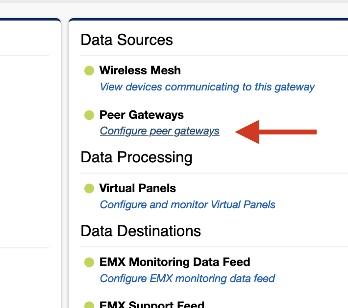
3. Once confirmed, click on the "Configure peer gateways" link.
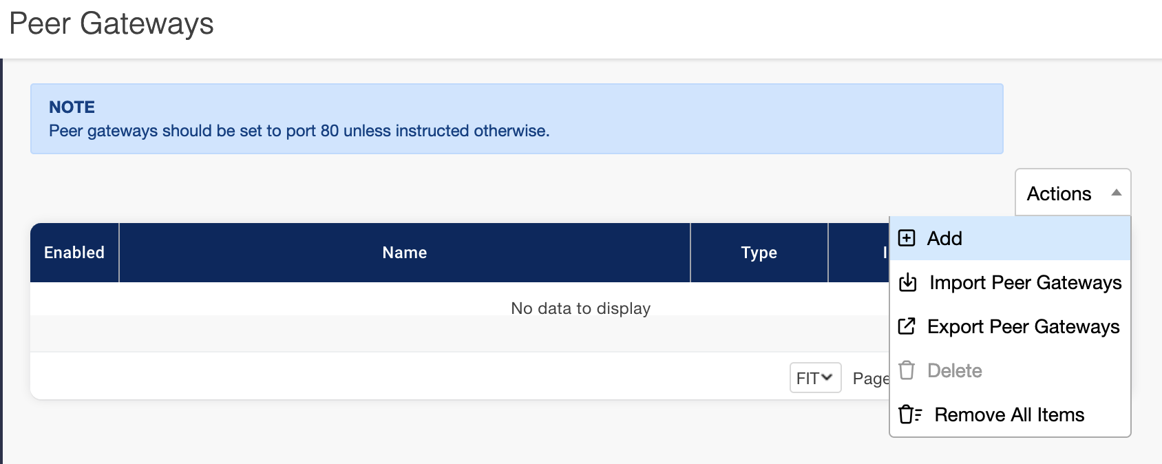
4. Click the add button under the Actions drop down to add peers to the master gateway.
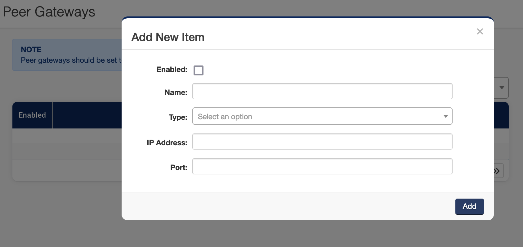
5. Complete the new item information.
a. Select "Enabled" to enable the device.
b. Assign whatever name you want for the peer.
c. Use the "Type" drop down to specify the gateway version - EG3 is Version 3 and EG4 is Version 4.
d. Supply the peer Gateway's IP address.
e. Set the Port to "80" unless you've been instructed otherwise.
f. When done, click the "Add" box.
Repeat the process to add more peer gateways. When you have established a master gateway, you may load and edit panel maps.
Load and Edit Panel Maps on Master Gateway
Once you have set up your master/peer gateway relationships, you can load the panel map to the master gateway.
1. Navigate to Data Processing → Virtual Panels in the master gateway left navigation bar.
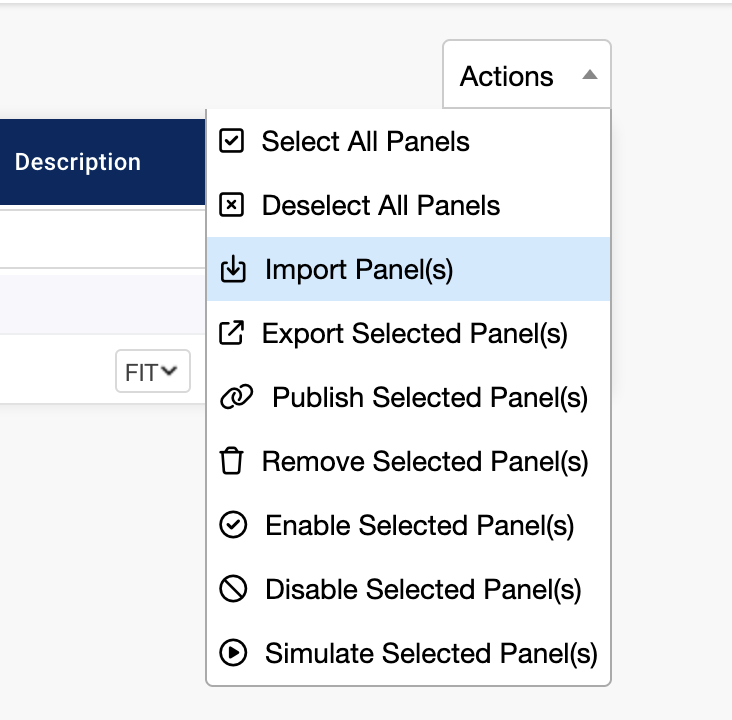
2. Use the Actions drop down menu to import the panel map file you received from Packet Power. Panel map files are unique for each monitoring device. The 16-digit ID on the device corresponds to a unique panel map file with the same 16-digit ID. Select "Import panel(s)" then select the local file you want to import into the gateway. Repeat this process for all panels you wish to import.
Edit Panel Maps
You may edit panels to reflect the layout of the equipment you are monitoring including creating circuit names that match your device.
Use the Edit pencil icon on the right to edit your desired Virtual Panel.
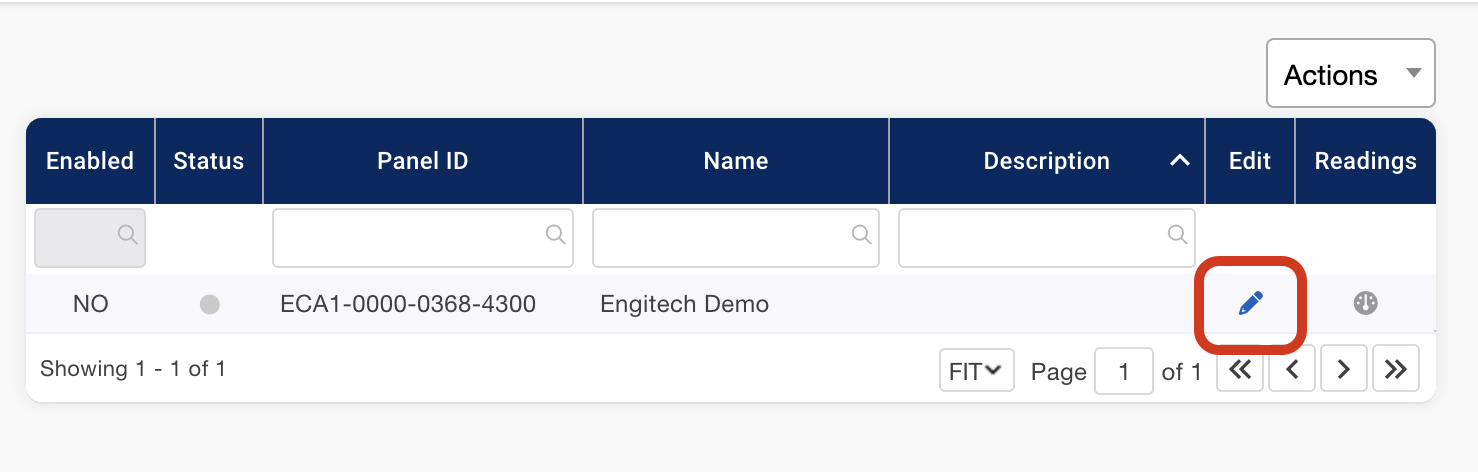
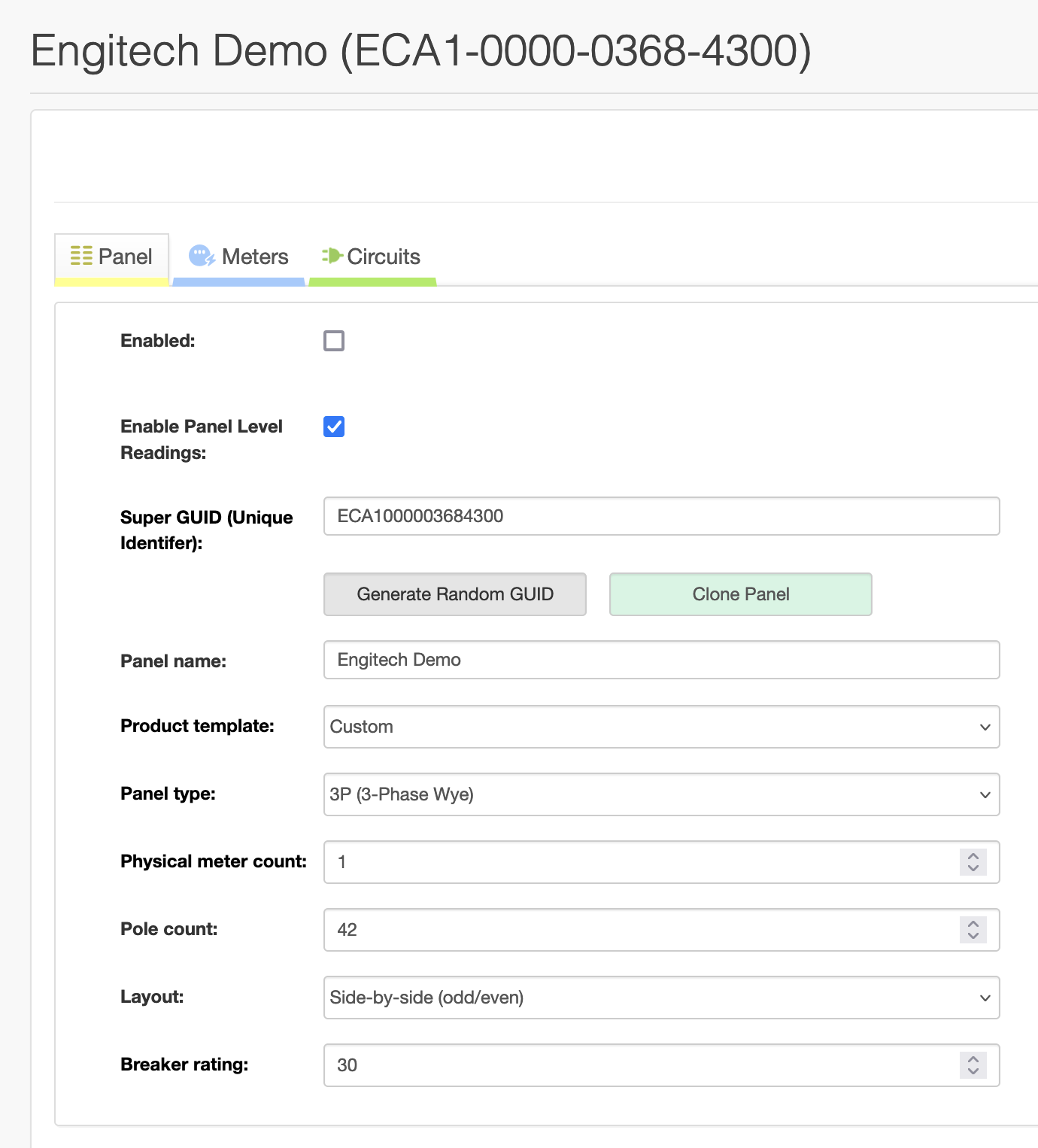
This brings up the full panel details.
-
Panel name -- editable in the "Additional Information" section
-
Panel GUID -- 16-digit ID that matches the BGXX device label GUID (not an editable field)
-
Task bar -- enables you to Disable/Enable Panel; Duplicate Panel; Export Panel; Publish to EMX; Remove Panel
-
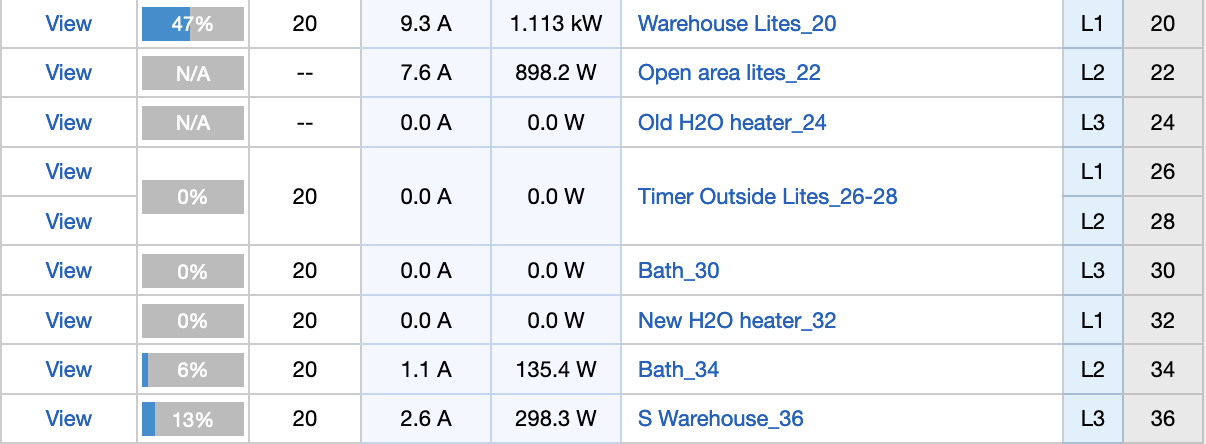
Panel status bar -- appears when the panel is active
-
Additional Information -- can be expanded to enable editing the panel name and description
-
Input Source Meter
-
Input Breaker/Source Rating
-
Circuit Details -- Pole (circuit number); Ph (circuit phase); CT (CT number); Type (circuit type); Rating (circuit rating in Amps); Name (circuit name)
Edit Panel Name and Description
Click on the content under "Name" to change the panel name that appears in all EMX reports along with the 16-digit panel GUID
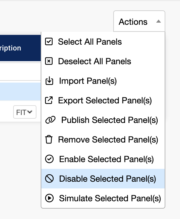
Panel must be disabled to edit any Virtual Panel settings or properties.
You can disable the panel with the disable panel option under the Actions Drop down.
Edit Input Breaker/Source Rating
-
If your BGXX device was configured to monitor the panel infeed circuits, you'll see a 16-digit GUID associated with the infeeds. If you elected not to include the infeed circuits in your panel map, you will see "Input Source Meter: Not set".
-
You may edit Input Breaker/Source Rating to reflect the amperage of your panel's infeed circuits. Click on the blue content to edit. This allows the system to do some calculations on how much input capacity is being used.
Edit Individual Circuit Details
Pole and Phase were provided to Packet Power as part of the panel map file creation. Please contact support@packetpower.com if the panel map file you received does not accurately reflect your panel. CT number is part of the panel map file as well and not generally a field you need to edit.
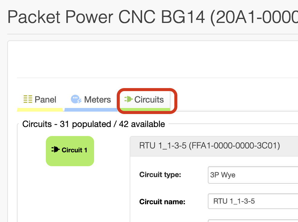
to make changes per circuit, enter the Circuits tab.
-
Circuit Type and Rating -- Select the type of circuit from the drop down menu.
[L-N] Single pole line-to-neutral circuit
[L-L] Two pole line-to-line circuit
[Wye] Three pole wye circuit
[Delta] Three pole delta circuit
[Unused] Blank, unused breaker
If you select three-phase delta or wye, the system will automatically assign three poles in sequence, beginning with the one you are editing, to define the circuit. Set the amperage rating for each pole by clicking in the Rating cell.
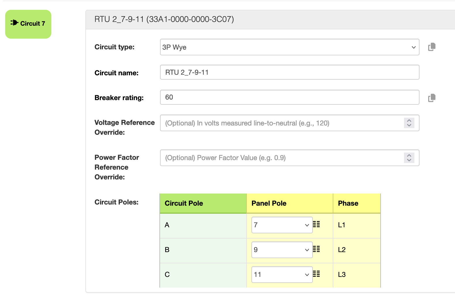
-
Circuit name -- The circuit name should be something meaningful for you as this is what appears in EMX. A best practice is to consider a short description of what is on the circuit as well as the pole position. This is especially helpful if the same type of equipment is monitored across multiple circuits. Click on the text to edit content or on the empty field to add content.
When you have finished editing the panel, click Save Panel in the panel task bar.
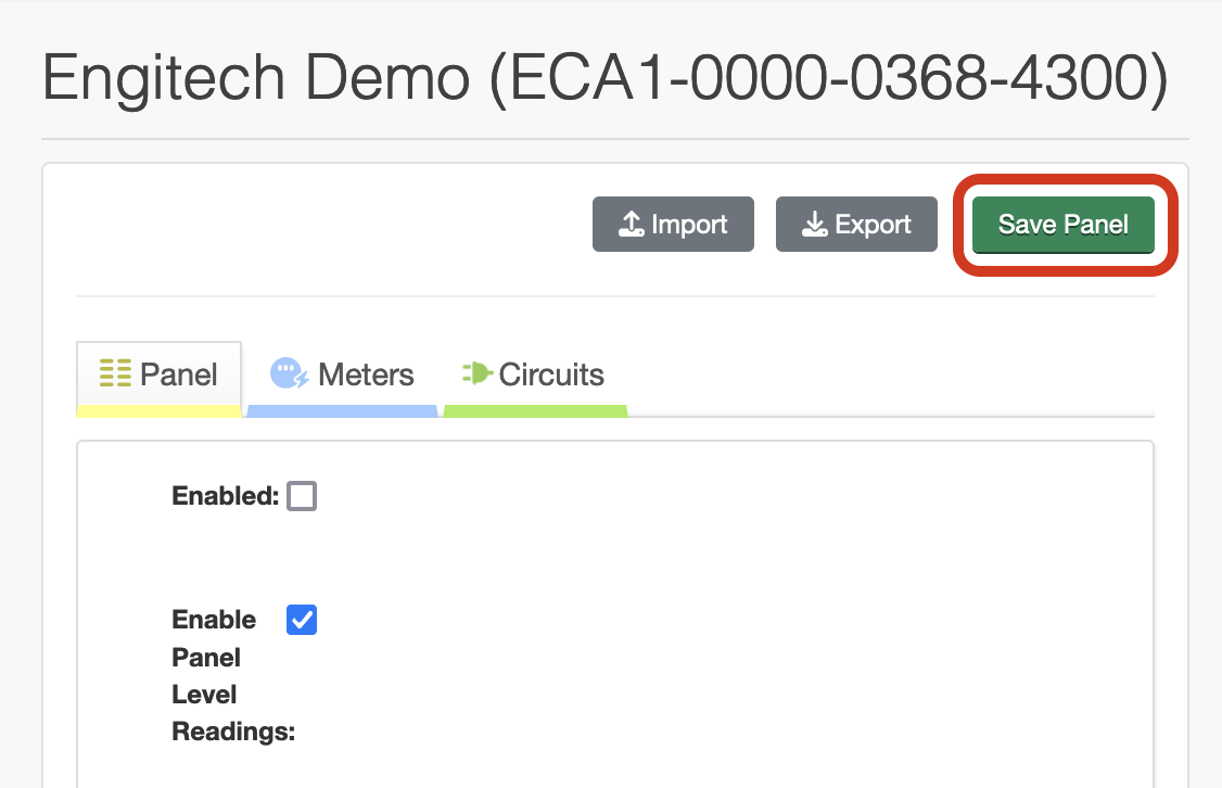
Click "Enabled" in the panel task bar to make the panel live in EMX. This automatically publishes the panel data to EMX and makes the data visible in the master gateway console.
View Panel Data in Gateway
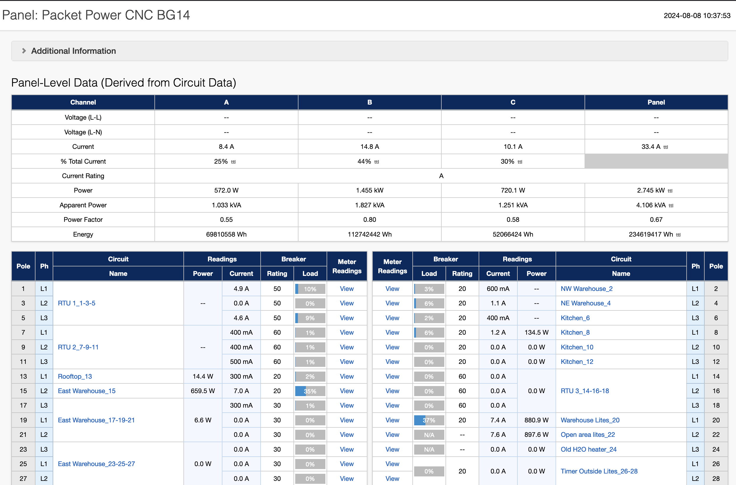
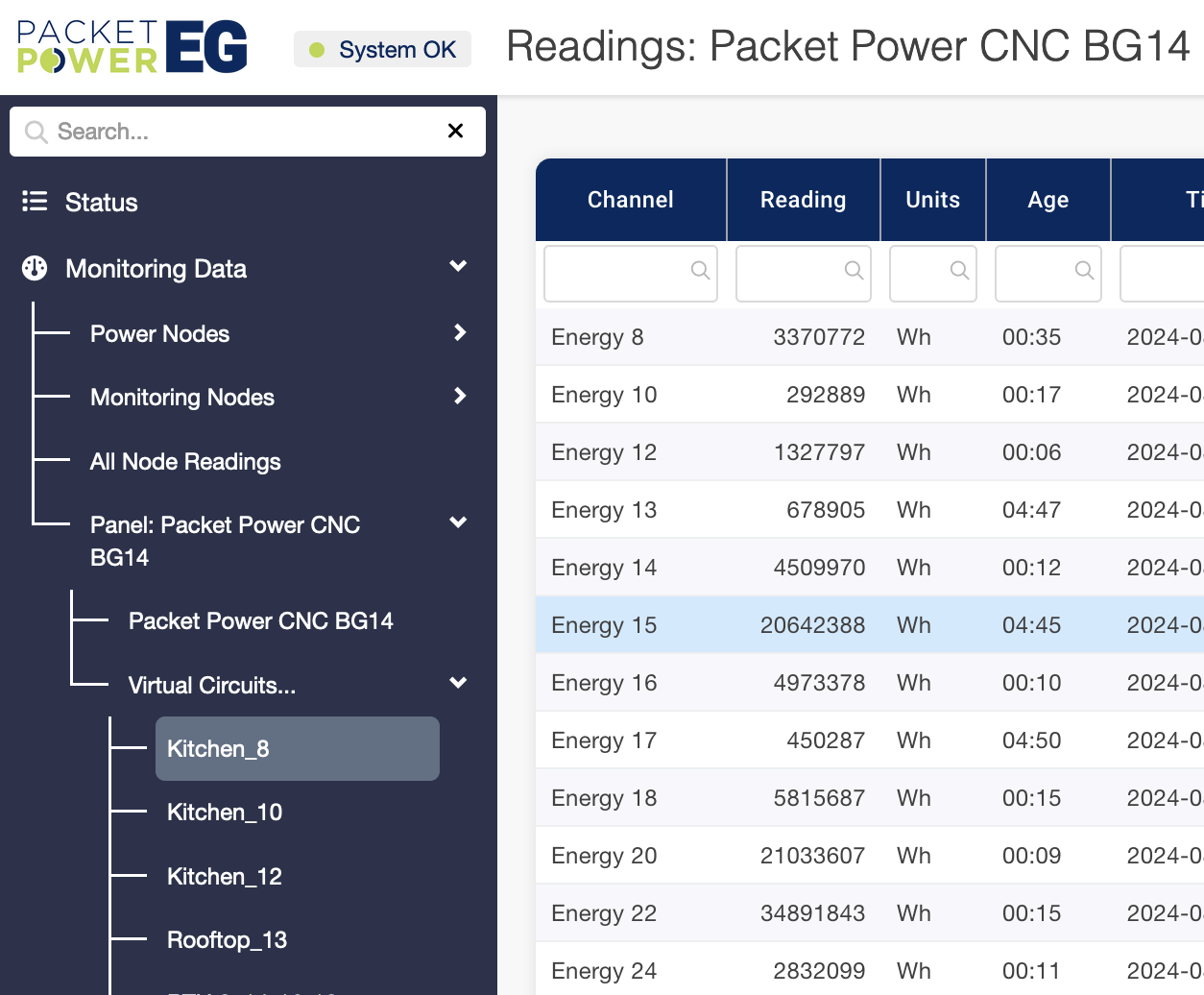
To view the overall panel data in the master gateway, expand Monitoring Data in the left navigation menu and the click the panel name below that.
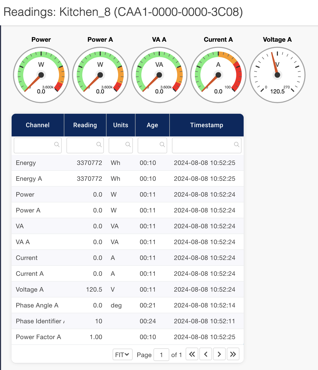
Click on an individual circuit to see monitoring details by circuit. You'll see the friendly circuit name in the left navigation and the virtual 16-digit GUID in the readings display.
Once a panel has been enabled, may you view the data in EMX if you are an EMX subscriber.
Device and Circuit GUIDs
Every Packet Power device has a unique 16-digit ID or GUID assigned.
-
Your BGXX monitoring device has a 16-digit GUID on a label attached to the device enclosure.
-
Virtual circuits are automatically assigned a 16-digit GUID when a panel is created. This virtual circuit ID appears in EMX.
-
Panel maps are unique by monitoring device and are assigned the same 16-digit ID as the device's GUID.
There is an association between device/panel ID and the virtual circuit IDs.
Device ID (same as Panel ID): 20A1-0000-0000-3C00
Virtual circuit ID: 3FA1-0000-0000-3C16
A1 will always be the 3rd and 4th digits of the 16-digit GUID for all panel device and virtual circuit IDs. This indicates the device is associated with a panel and that the virtual circuit is part of a panel.
The 7th through 14th digits will be the same for a device/panel ID as for the virtual circuits associated with that specific panel. These 8 digits will be unique to a specific panel and its corresponding virtual circuits.