

Summary
The MP277 generation of Packet Power power meters provides significant improvements over the prior generation in three areas:
-
An increase in the number of CTs per meter from 3 up to 8 (depending on the model)
-
The ability to automatically detect the voltage phase associated with each current reading
-
The ability to calculate total load by phase
The new capabilities combine to offer these benefits:
-
Allow one meter to monitor multiple circuits
-
Support any mix of CT counts by voltage line
-
Accurately assign load by phase across a wide range of voltage mixes
-
Reduce the need to configure the meter for different types of voltage service
For example, a meter with 6 CTs could be used to monitor six loads all with a L1-N V source, a mix of 2 CTs on each of L1, L2 and L3, or two 3-phase wye circuits. Because the meter automatically detects the voltage phase associated with each load, it reports power accurately for each of the six sensor readings. It can also aggregate and report the load by phase (L1, L2 and L3) and, in the case of the two 3-phase circuits, report total usage for each of the the two circuits. This is possible without having to change the configuration of the meter.
In order to take advantage of these new capabilities, customers may need to update the way they consume data from the meters by, for example, modifying the Modubs registers used or updating their SNMP MIBs. The products involved include any product beginning with MP277 (e.g. MP277-8MV).
Reading Types
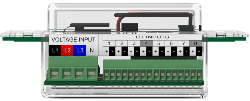
Voltage: The meter can accommodate 1 to 3 voltage inputs (plus neutral). They are labeled L1, L2 and L3 on the meter. Meters can report up to 6 voltage readings, 3 line-to-neutral readings (with the conductor wired to L1 reported as VoltageA, L2 as VoltageB), and L3 as VoltageC), 3 line-to-line readings (reported as VoltageAB, VoltageBC, and VoltageCA). The meter also calculates voltage phase angles.
Sensor: The number of sensor readings depends on the number of CTs attached to the meter. Different models support from 1 to 8 CTs. Sensor readings are differentiated by number, e.g. Current1, Current2, Current3, etc. Current, volt amps, power, energy, phase angle and power factor are reported at the sensor level. The meter also reports the "phase ID" indicating which line (A, B or C) the sensor is used on.
Aggregate by line: Sensor-level readings for current, power and energy are added together to show total usage by line. These readings are denoted by letter, e.g. PowerA, PowerB and PowerC. Current, volt amps, power, energy, phase angle and power factor are reported at the aggregate level. CurrentN is also reported.
Aggregate by Sub-circuit: In certain circumstances, meters may also be programmed to report "subtotals" to show total power, energy, and volt amps by circuit if a single meter is used to measure usage from multiple circuits. These readings are accessed using specific addresses (e.g. a Modbus register).
Certain circuit types (for example 3-wire "delta" circuits in which no neutral is present) report a different mix of readings.
Examples
The following examples show how power readings from a meter with 6 CTs differ based on different types of voltage sources.
4-wire "WYE" L1, L2, L3 and N
Physical Wiring
|
Terminal |
Line |
|---|---|
|
L1 |
L1 |
|
L2 |
L2 |
|
L3 |
L3 |
|
N |
N |
By Sensor
|
CT Terminal |
Channel |
Reading |
Units |
Voltage Line |
|---|---|---|---|---|
|
1 |
Power1 |
210 |
Watts |
L1 |
|
2 |
Power2 |
214 |
Watts |
L2 |
|
3 |
Power3 |
212 |
Watts |
L3 |
|
4 |
Power4 |
604 |
Watts |
L1 |
|
5 |
Power5 |
612 |
Watts |
L2 |
|
6 |
Power6 |
598 |
Watts |
L3 |
Aggregate by Line
|
Terminal |
Channel |
Reading |
Units |
Sensors |
|---|---|---|---|---|
|
L1 |
PowerA |
814 |
Watts |
1 and 4 |
|
L2 |
PowerB |
826 |
Watts |
2 and 5 |
|
L3 |
PowerC |
810 |
Watts |
3 and 6 |
3-wire "split phase" L1, L2 and N
Physical Wiring
|
Terminal |
Line |
|---|---|
|
L1 |
L1 |
|
L2 |
L2 |
|
L3 |
Not used |
|
N |
N |
By Sensor
|
CT Terminal |
Channel |
Reading |
Units |
Voltage Line |
|---|---|---|---|---|
|
1 |
Power1 |
210 |
Watts |
L1 |
|
2 |
Power2 |
214 |
Watts |
L2 |
|
3 |
Power3 |
212 |
Watts |
L1 |
|
4 |
Power4 |
604 |
Watts |
L2 |
|
5 |
Power5 |
612 |
Watts |
L1 |
|
6 |
Power6 |
598 |
Watts |
L2 |
Aggregate by Line
|
Terminal |
Channel |
Reading |
Units |
Sensors |
|---|---|---|---|---|
|
L1 |
PowerA |
1,034 |
Watts |
1, 3 and 5 |
|
L2 |
PowerB |
1,416 |
Watts |
2, 4 and 6 |
|
L3 (not used) |
PowerC |
-- |
Watts |
|
2-wire all loads on L2
Physical Wiring
|
Terminal |
Line |
|---|---|
|
L1 |
Not used |
|
L2 |
L2 |
|
L3 |
Not used |
|
N |
N |
By Sensor
|
CT Terminal |
Channel |
Reading |
Units |
Voltage Line |
|---|---|---|---|---|
|
1 |
Power1 |
210 |
Watts |
L2 |
|
2 |
Power2 |
214 |
Watts |
L2 |
|
3 |
Power3 |
212 |
Watts |
L2 |
|
4 |
Power4 |
604 |
Watts |
L2 |
|
5 |
Power5 |
612 |
Watts |
L2 |
|
6 |
Power6 |
598 |
Watts |
L2 |
Aggregate by Line
|
Terminal |
Channel |
Reading |
Units |
Voltage Line |
Sensors |
|---|---|---|---|---|---|
|
L1 (not used) |
PowerA |
-- |
Watts |
|
|
|
L2 |
PowerB |
2,450 |
Watts |
L2 |
1 - 6 |
|
L3 (not used) |
PowerC |
-- |
Watts |
|
|
Accessing data using standard protocols
In general, the "Aggregate by Line" values are used as the equivalent to the readings produced by our earlier metering products. So, as an example, PowerA for the MP277 uses the same Modbus register in our standard register map that PowerA did for earlier meters. On circuits with 3 CTs and L1/L2/L3/N voltage connections, the MP277s and our older meters will report the same data. However, in other combinations of CTs and voltage phases, the new meter will behave differently than the old meter.
The most reliable way of accessing data from the new meter is to use the new sensor-level readings as the main source of information, and rely on the A / B / C aggregate readings as aggregates only. Changes have been made to standard protocol implementations to support the additional readings.
For example, the following table shows how our standard register map has changed in Modbus.
|
Channel |
Old Meter Register |
Old Meter Expression |
MP277 Register |
MP277 Expression |
|---|---|---|---|---|
|
PowerA |
1 |
R(PowerA) |
1 |
R(PowerA) |
|
PowerB |
2 |
R(PowerB) |
2 |
R(PowerB) |
|
PowerC |
3 |
R(PowerC) |
3 |
R(PowerC) |
|
Power1 |
N/A |
N/A |
4 |
R(Power1) |
|
Power2 |
N/A |
N/A |
5 |
R(Power2) |
|
Power3 |
N/A |
N/A |
6 |
R(Power3) |
|
Power4 |
N/A |
N/A |
7 |
R(Power4) |
|
Power5 |
N/A |
N/A |
8 |
R(Power5) |
|
Power6 |
N/A |
N/A |
9 |
R(Power6) |
Specific details for all supported protocols can be found here.
Other considerations
As with prior meters, on three-wire delta circuits (L1-L2-L3), the voltage inputs are wired with L3 connected to the N input on the meter. On these circuits, only current is reported at the sensor level.
Packet Power has the ability to configure meters to behave in specific ways to better suit certain tasks. For example, when meters are used in our BGPxxx branch circuit monitoring product line there is no value in reporting the aggregate A, B and C readings so they are disabled.
The MP227's ability to automatically detect voltage phases minimizes the need to configure meters, simplifies installation, and allows maximum flexibility. However, in order for auto phase detection to function properly, the following must be true:
-
It must be enabled in the meter's firmware
-
The CTs must be oriented properly on the conductors
-
There must be load present on the circuit
In some circumstances, it may be preferable to disable auto phase detection and assign specific voltage phases to each sensor. If, in this case, either the voltage lines are not connected properly to the meter or the sensors are installed on the incorrect voltage lines, current will report correctly but other readings may be incorrect.
Other resources
Additional information is available in online support including: