

NOTE: Modbus register maps are pre-loaded on Gateways with firmware versions 1.12.0 or higher. These register maps have static / pre-assigned register numbers. It is suggested that any Gateway (GW04) be upgraded to firmware version 1.12.0 or higher rather than importing register maps.
Legacy register maps may be download from the below links:
EG4 Modbus Overview
The Wireless Gateway Modbus interface makes all monitoring data received from Packet Power's wireless monitoring network accessible via standard Modbus TCP/IP protocol via the Ethernet port of the Gateway. The Gateway is capable of providing a Modbus data output and simultaneously serving data to EMX portal. This allows users to take advantage of the EMX portals features while also serving data to the third party monitoring system.
The Wireless Gateway appears as a standard Modbus device listening on port 502 at the IP address of the Gateway. Individual monitoring nodes have distinct Modbus slave IDs. If more than 254 nodes are present, multiple nodes may report at the same slave ID under different register ranges (see Register Mapping section below). The Modbus protocol requires a single Master connection for all connected nodes.
.svg?cb=e6a8eababf5a68af09cceab52f0ae53a)
Peering Gateways and Using a Master Gateway
Packet Power Gateways can be deployed in a master / peer relationship. In this approach, the master gateway gathers data from all of its peers. This makes it easier for monitoring applications to access data as the monitoring application only needs to communicate with the master gateway. Note that all peered Gateways must have support for Modbus protocol conversion. Refer to the peering section of the Data Sources guide for instructions on peering Gateways.
Note that in a network consisting of a mix of EG2, EG3 and EG4 Gateways, an EG4 must be designated as the master.

Enabling Modbus Output
To enable Modbus output, access the Gateway Console:
-
Make sure your Gateway is configured with an IP address and accessible on your network.
-
The Gateway must be connected to a switch /router on an accessible network. It may not be accessible directly through a PC Ethernet to Gateway connection in all cases.
-
Enter the IP address of the Gateway on any browser to access the Gateway Console.
For Gateway network configuration instructions follow this link.

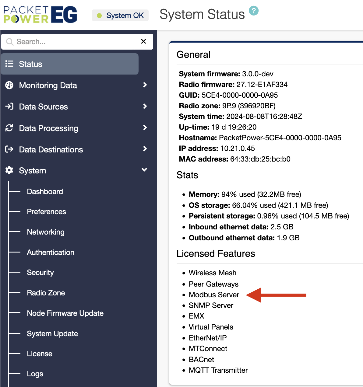
Once the Console appears, it will present a System status screen. Validate:
-
The system is communicating properly with the monitoring nodes as indicated by a green “System Ok” status light
-
Modbus is listed as a licensed feature. If not ,see the licensing section on how to add a license.
Enabling and Configuring the Modbus Driver
-
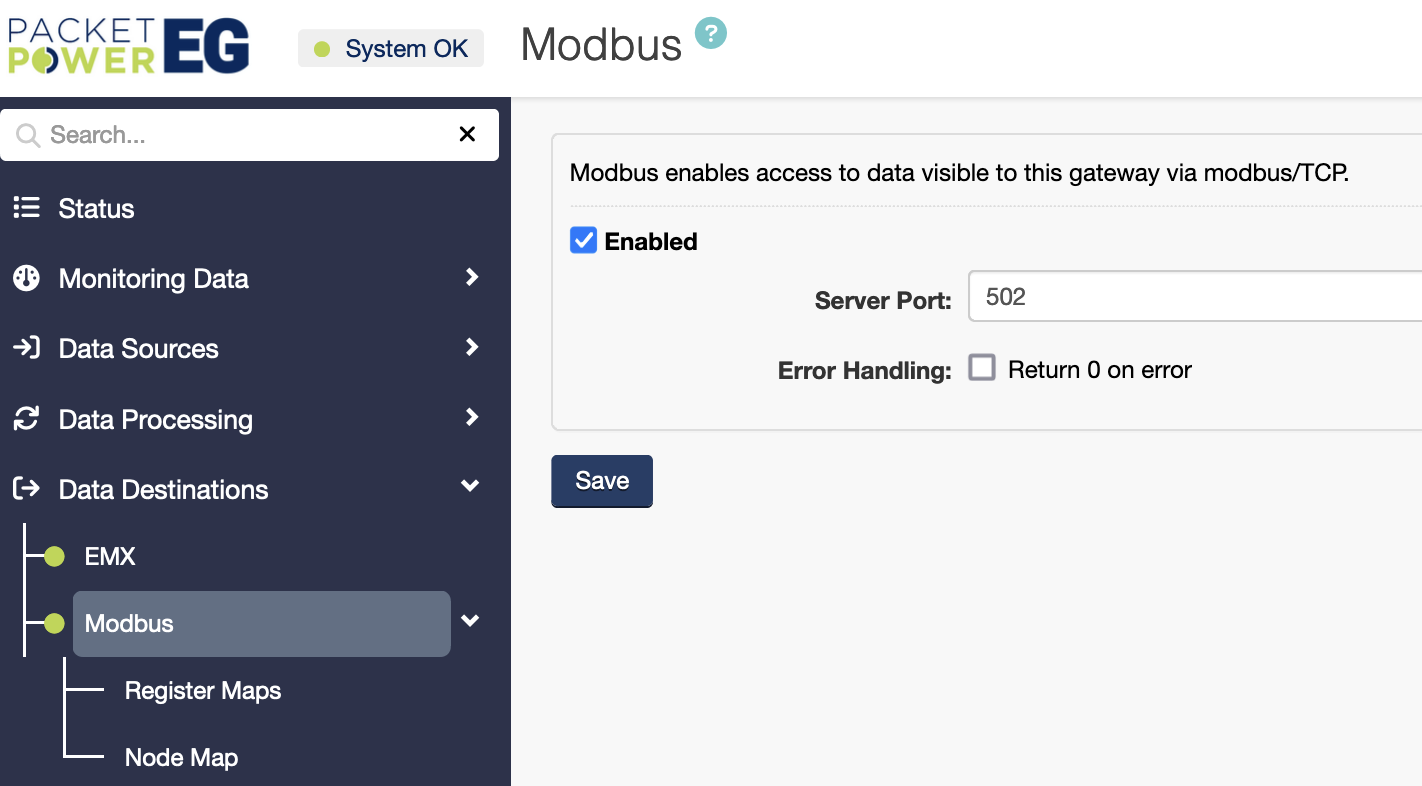
To enable the Modbus driver, navigate to Data Destinations → Modbus.
-
Make sure that the “Enabled” check box is checked
-
Enter the port number to be used. This is typically port 502
-
Click “Save” to enable the selections.
Once enabled, there will be a green light next to the Modbus tab.
Viewing and Verifying Monitoring Data using the Gateway Console
To view data for monitoring nodes associated with the Gateway and confirm operation of specific nodes select the “Monitoring Data” tab on the Gateway Console.
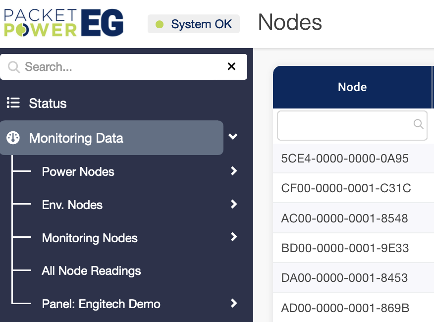
This will display all connected nodes which are organized by type (power and environmental) in the sub-menu
To search for a specific node enter the GUID (16 digit node ID) in the nav bar search or “Node” column.
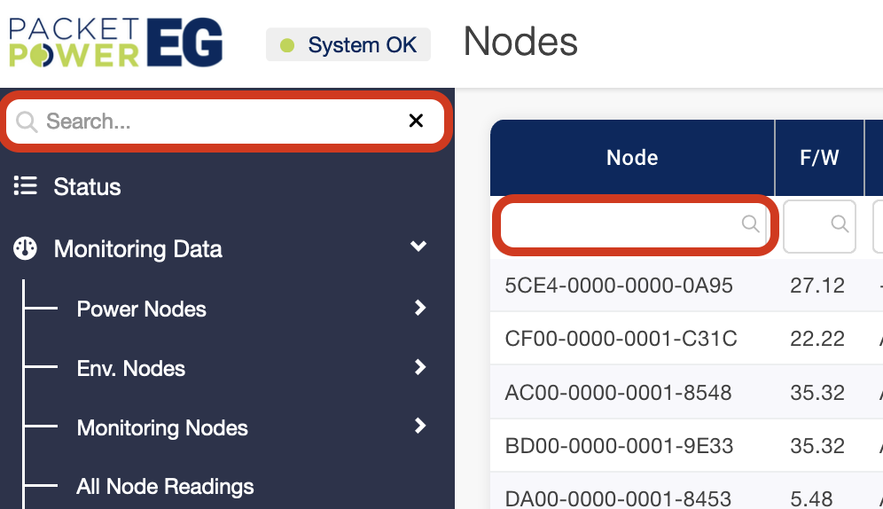
To access specific readings for each node click on the “readings” icon to expose the real time readings.
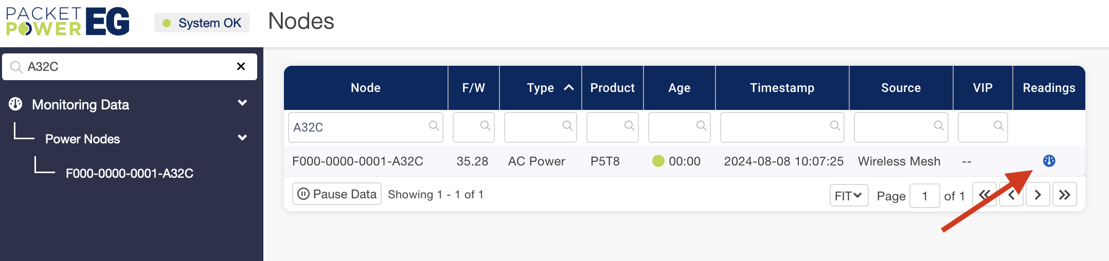
An explanation of the readings data can be found here.
Accessing Register Maps Maps
Depending on your Gateway, register maps may be pre-loaded on Gateways with firmware versions 1.12.0 or higher and will appear under the Modbus Register Maps table.
Your register maps can be imported if they are not pre-populated.
Importing and Exporting Register Maps
-
To import a register map, navigate to Data Destination → Modbus → Register Maps.
-
Click on the import or export options under the actions drop down.
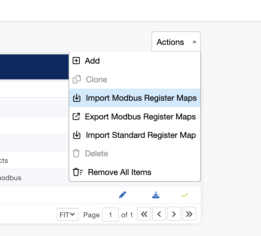
For imports, specify the register file to be imported; the map will appear in the “Modbus Register Maps” table.
This process can be used to export register maps for back-up and transfer to other Gateways.
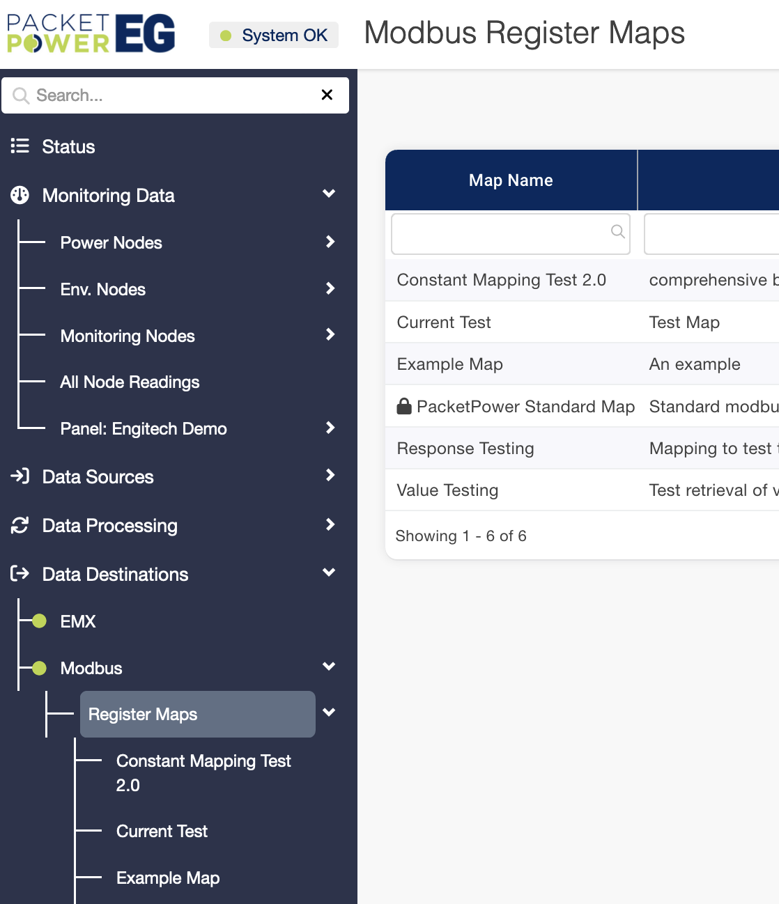
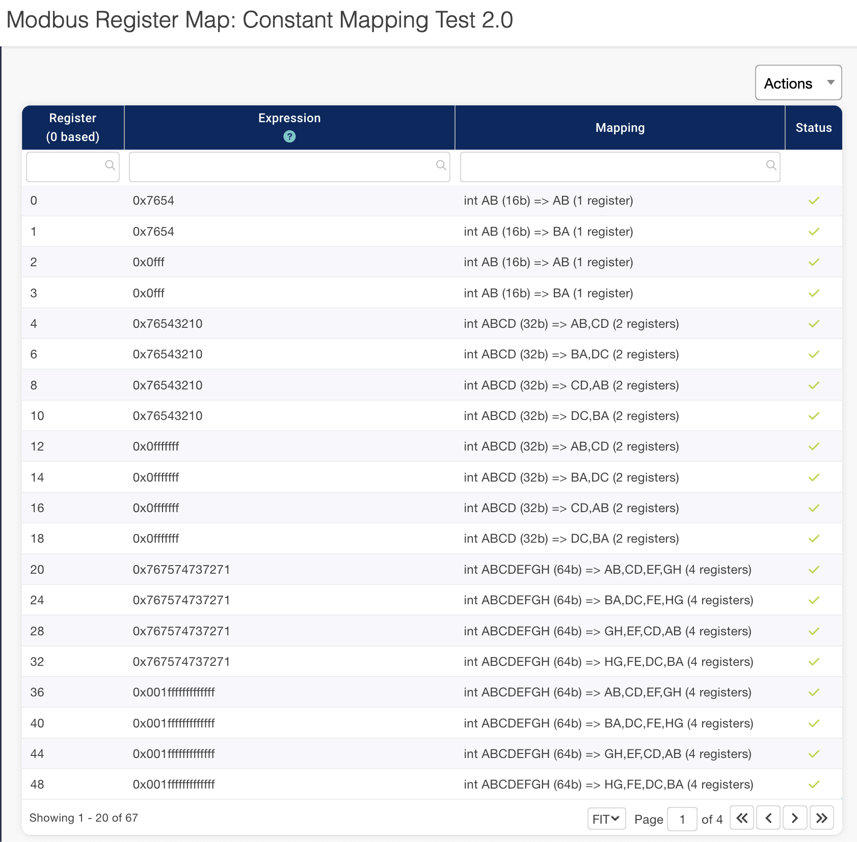
Viewing Register Maps
Once a register map is loaded or populated it can be accessed in “Register Maps” under Data Destinations → Modbus → Register Maps.
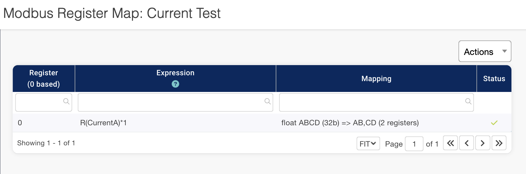
Each register has a status column to indicate the validity of the register; if the register is reading properly it will have a green check mark.
Register maps are explained in detail in the Register Maps section which explains Register features including Addressing Options, Offsets, Expressions and Mapping.
Manually Assigning Registers and Register Maps
Individual registers and register maps can be added or removed as needed.
Creating Register Maps
To create a new register map:
-
Navigate to Data Destinations → Modbus → Register Maps.
-
Select the add option under the Actions drop down.
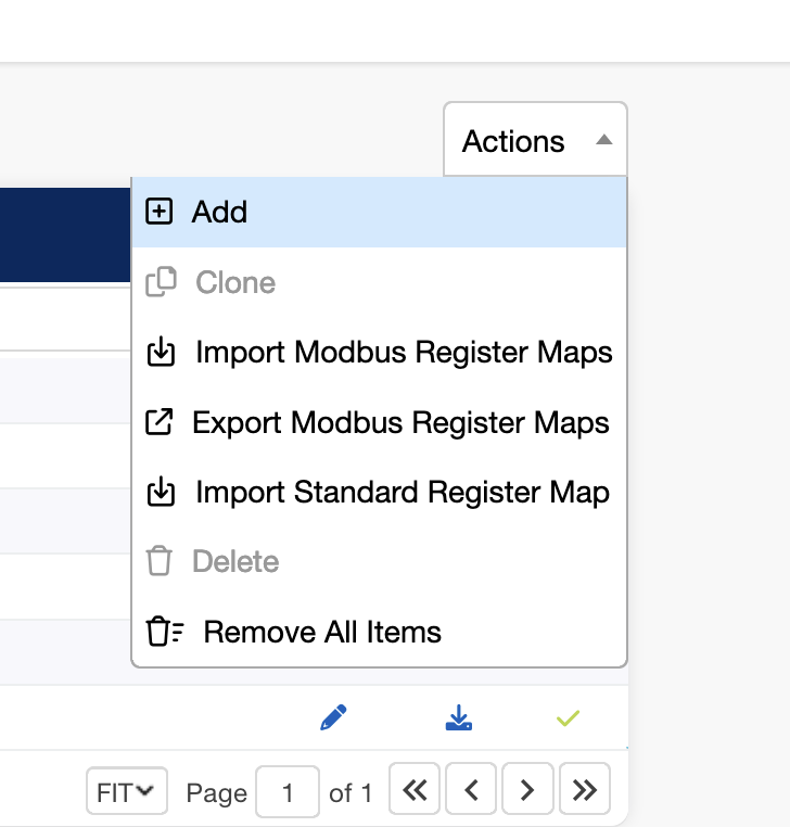
-
provide a Map Name and Description for the register map
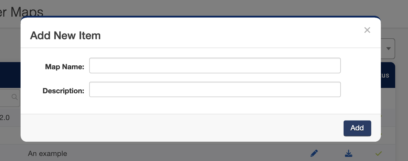
-
Click “Add” to save the selection.
Creating Registers
To access and add registers:
-
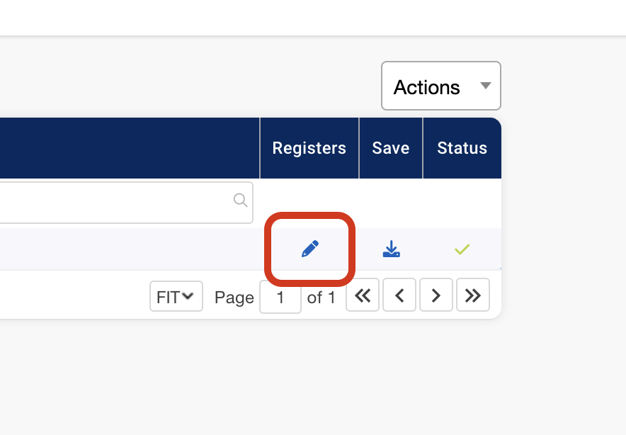
Select the “Register Maps” menu and highlight the specified register map
-
Click on the “pencil” icon under the Register Maps table; this will expose the registers.
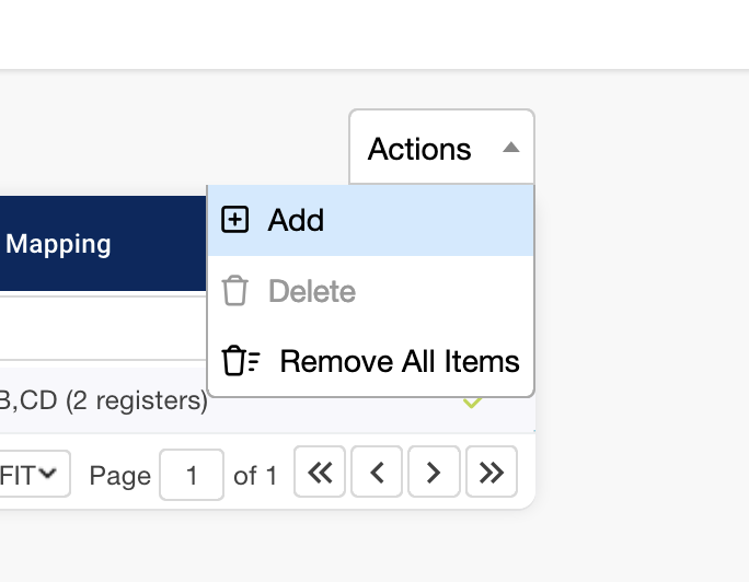
Adding Registers to Register Maps
To add individual registers to a register map select Add option from the Actions drop down.
Enter the Register, Expression and Mapping.
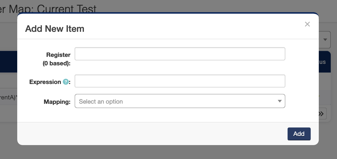
For more details on these items see the Register Mapping section.
Modbus Device IDs
Node Maps serve to assign “device IDs” and register maps to specific monitoring nodes. Modbus is limited to 255 unique device IDs (0-254) per master.
To allow more than 255 devices to serve under one master i.e. Gateways, different nodes can share a device ID but utilize register offset mapping.
Register Offset Node mapping
The Packet Power system supports large numbers of devices reporting through a single gateway. Up to 2000 nodes are supported in the Modbus Enterprise version.
Accessing and Verifying Modbus Readings Using the Gateway Console
To access and verify Modbus readings:
-
Select the “Readings” tab under Data Destinations → Modbus → Register Maps → Readings.
-
A table containing all Modbus readings will be displayed allowing for easy verification.
Exporting Modbus Readings
Readings can also be exported by selecting the export options under the Actions Drop down in Monitoring Data → All Node Readings.. The files are exported in .CSV or JSON format and can be viewed in a standard spread sheet.
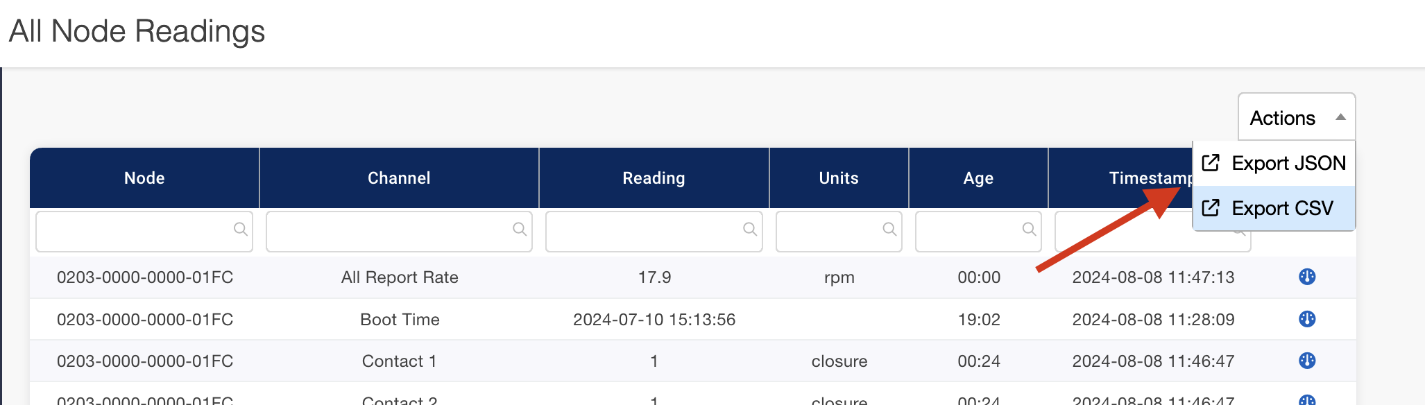
Note that readings should match the readings shown in the Monitoring Data tab.