

This guide provides instructions for integrating a Packet Power Wireless Network Connector (WNC) with BayTech Modular Metered Power units (MMPs) that feature outlet current and outlet power readings. This guide is applicable to MMPs set to factory default settings or those that can be reset to factory defaults.
Installation Process
Identify MMP
This guide applies to the following MMPs:
|
BayTech Model # |
Firmware version |
|---|---|
|
MMP-10 |
F5.13.01 |
Configure MMP
-
Factory reset MMP-10. Please refer to Baytech MMP manual for instructions.
-
Access MMP’s Command Line Interface
-
Connect computer’s USB port to the MMP’s
USB 1port. Upon connection, expect your computer to identify a new serial port -
Use PuTTY to open a connection to the serial port. Use 9600 baud rate.
-
Expect
Welcome to BayTech Universal PD login: -
Provide default login credentials
-
root -
baytech
-
-
-
Configure
ETHERNET 1port to a static IP address of 192.168.1.10-
Disable DHCP by choosing this sequence of options
-
Configure...................................C-
Network Port Configuration......8-
DHCP Enable/Disable...............6-
10/100 network port...............1 -
Enable ? (Y/N), CR for no change)TypeN
-
-
-
-
-
Return to Network Port Configuration menu
-
Hit
Entertwice to return to the Network Port Configuration Menu
-
-
Set Static IP address fields by choosing this sequence of options
-
IPv4 Configuration................1-
10/100 network port...............1 -
IP Address........................1-
192.168.1.10
-
-
Subnet Mask-
255.255.255.0
-
-
-
-
Return to Network Port Configuration Menu
-
Hit
Enteruntil prompted with the Network Port Configuration Menu
-
-
Verify SNMP settings
-
SNMP Configuration................11-
SNMP Enable.......................7-
SNMP is ENABLED. Enable? (Y/N):TypeY
-
-
SNMP Read-Only Community..........5-
Read Community Name: public
-
-
-
-
Connect WNC to MMP
-
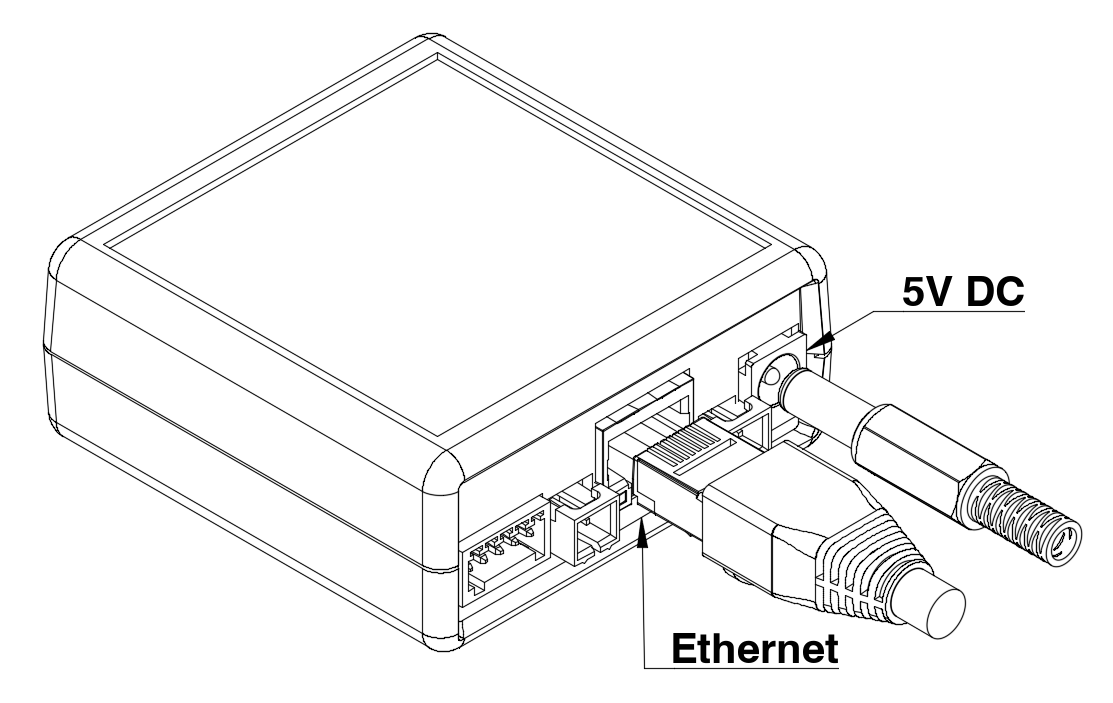
Connect ethernet cable into the WNC RJ-45 port.
-
Connect plug side of WNC power cable into the WNC 5VDC power jack.
-
Connect the other end of ethernet cable into the MMP-10’s ETHERNET 1 port
WNC Connections
MMP Connections
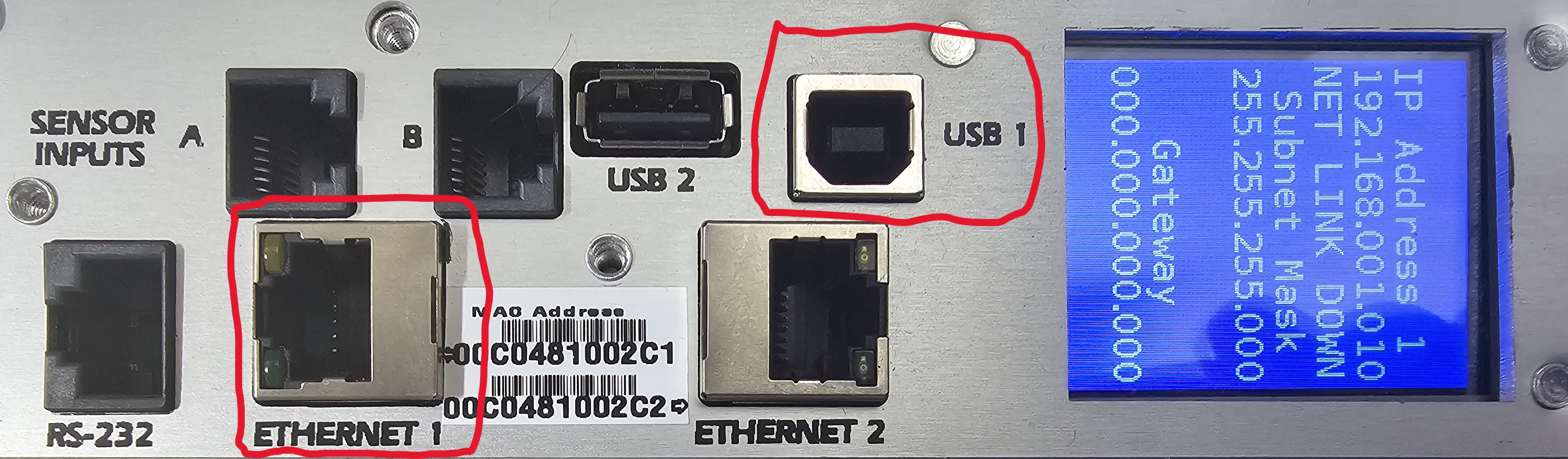
USB 1: Use for PDU configuration
ETHERNET 1: Use for WNC communications
Verify Connection
-
The WNC Display rotates through messages periodically after power-up.
-
Wait up to 8 minutes for the scan loop to identify the MMP-10.
-
Expect display to show
State:Poll, which indicates a successful connection.
-
Verify Readings
-
Use the Packet Power Gateway Web Console to verify that readings are received.
-
Readings will be associated with the 16 hex digit identifier printed on the WNC QR code.
The following readings should appear and update approximately every minute.
|
Channel |
Description |
|---|---|
|
Current 1..36 |
outlet current (1..36) |
|
Power 1..36 |
outlet power (1..36) |