

Introduction
HDPM is an ultra-high density power monitoring system supporting up to 120 multi-phase circuits. It is highly-modular and designed to fit in almost any equipment and configuration with minimal installation effort. It can be easily deployed within existing equipment as well as embedded into new systems.
.gif)
.gif)
.gif)
Key components
HDPM consists of the following key components:
-
Monitoring module
-
Power supply
-
Sensor interfaces
-
PPBUS connections
-
Current sensors (a.k.a. CTs)
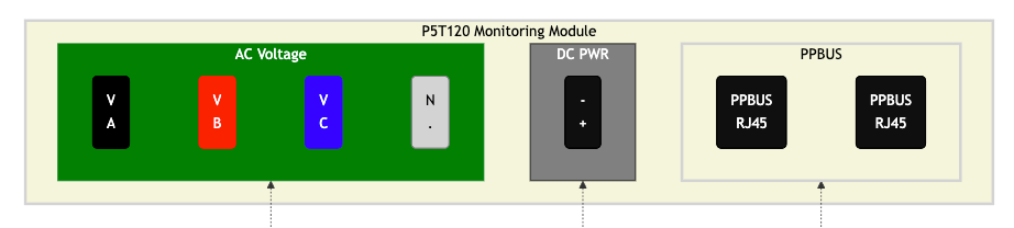
Monitoring module
The HDPM monitoring module is the main component of the system. It interfaces with the voltage lines and the current sensors in order to perform real-time power monitoring. It is also responsible for transmitting monitoring data to the Packet Power gateway using the wireless mesh network.
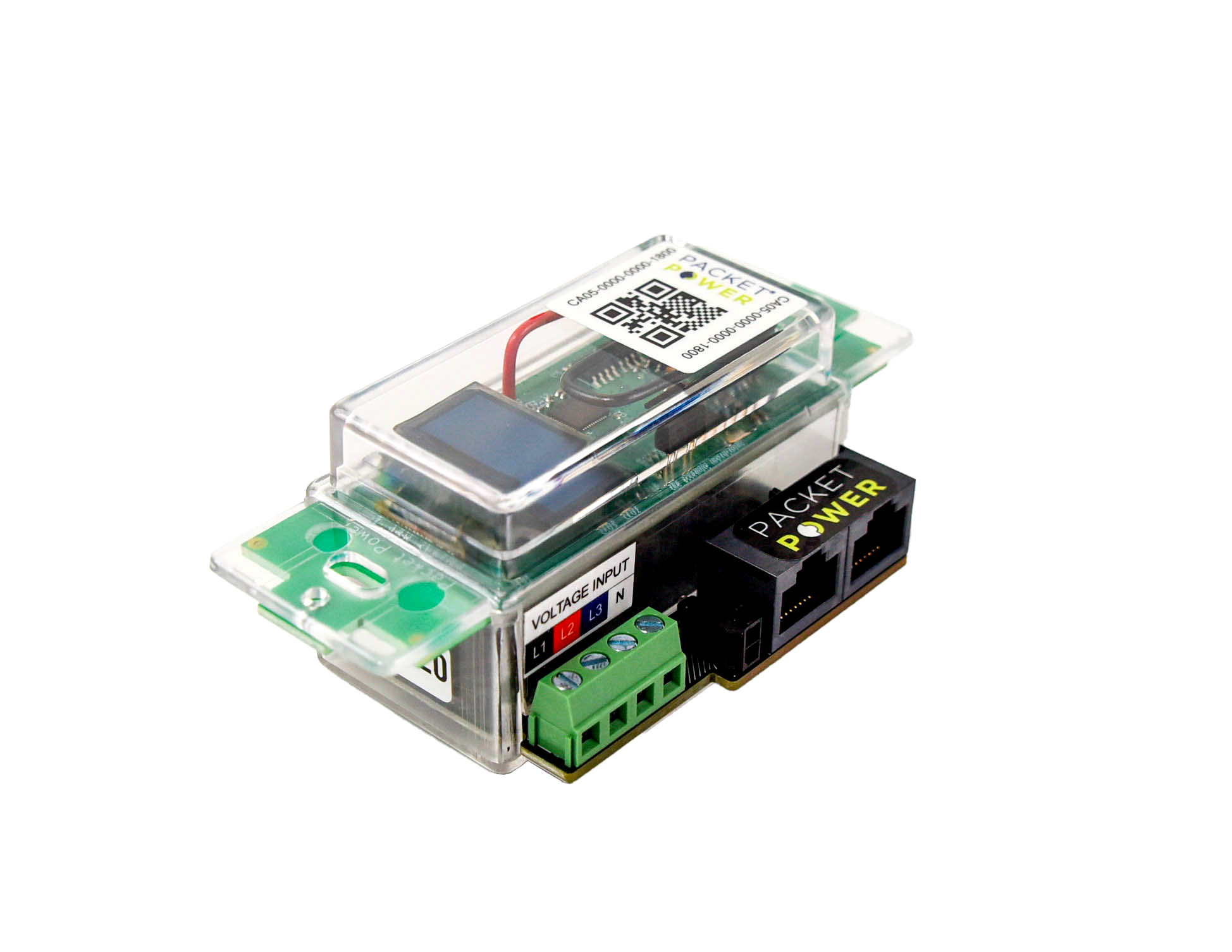
The HDPM monitoring module has three connections:
-
4-pin voltage interface block, supporting 1, 2 or 3-phase (Wye & Delta) connections
-
24V DC power interface, supplying power to the system
-
2 RJ-45 PPBUS connectors providing connections to the current sensor interfaces
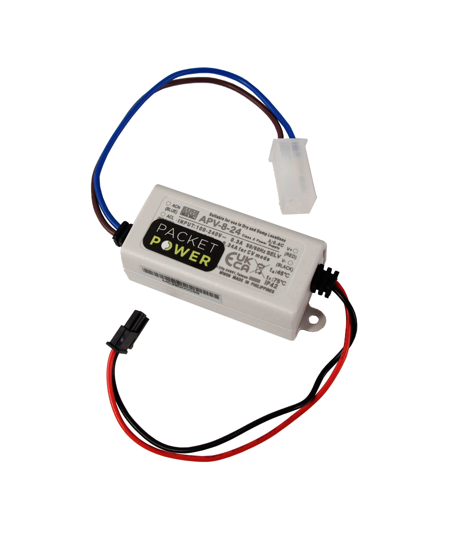
Power supply
The HDPM system uses a 24VDC power supply. It provides power completely independent of the monitored circuit(s). The power supply AC input can optionally be connected to one of the monitored phases. The HDPM can be configured to support multiple, redundant power sources if necessary. Please contact Packet Power technical support if that is required.
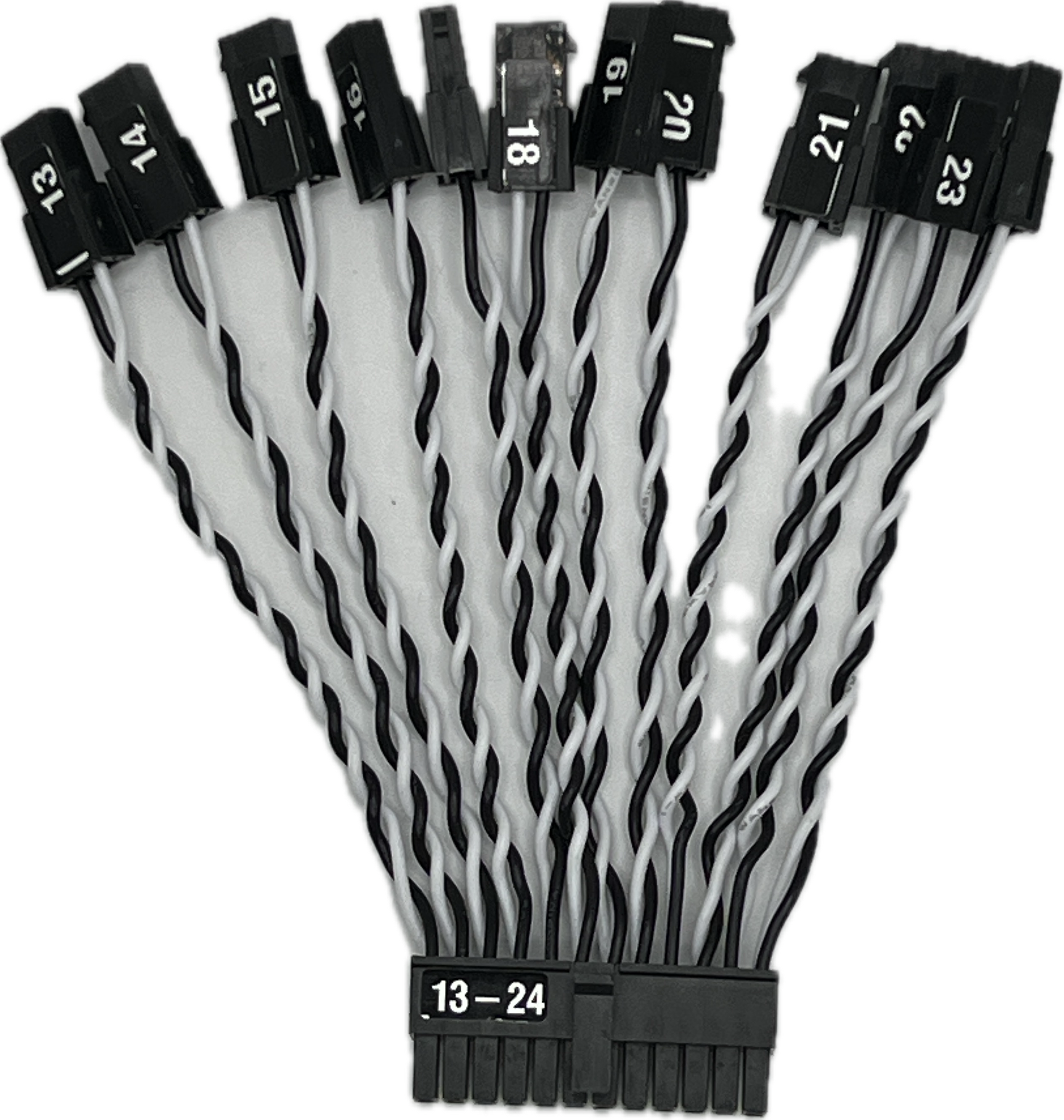
Sensor interfaces
HDPM uses sensor interfaces to connect to current sensors. Each sensor interface supports up to 12 current sensors. Each sensor interface is unambiguously labeled indicating the sensor numbers connected to the interface.
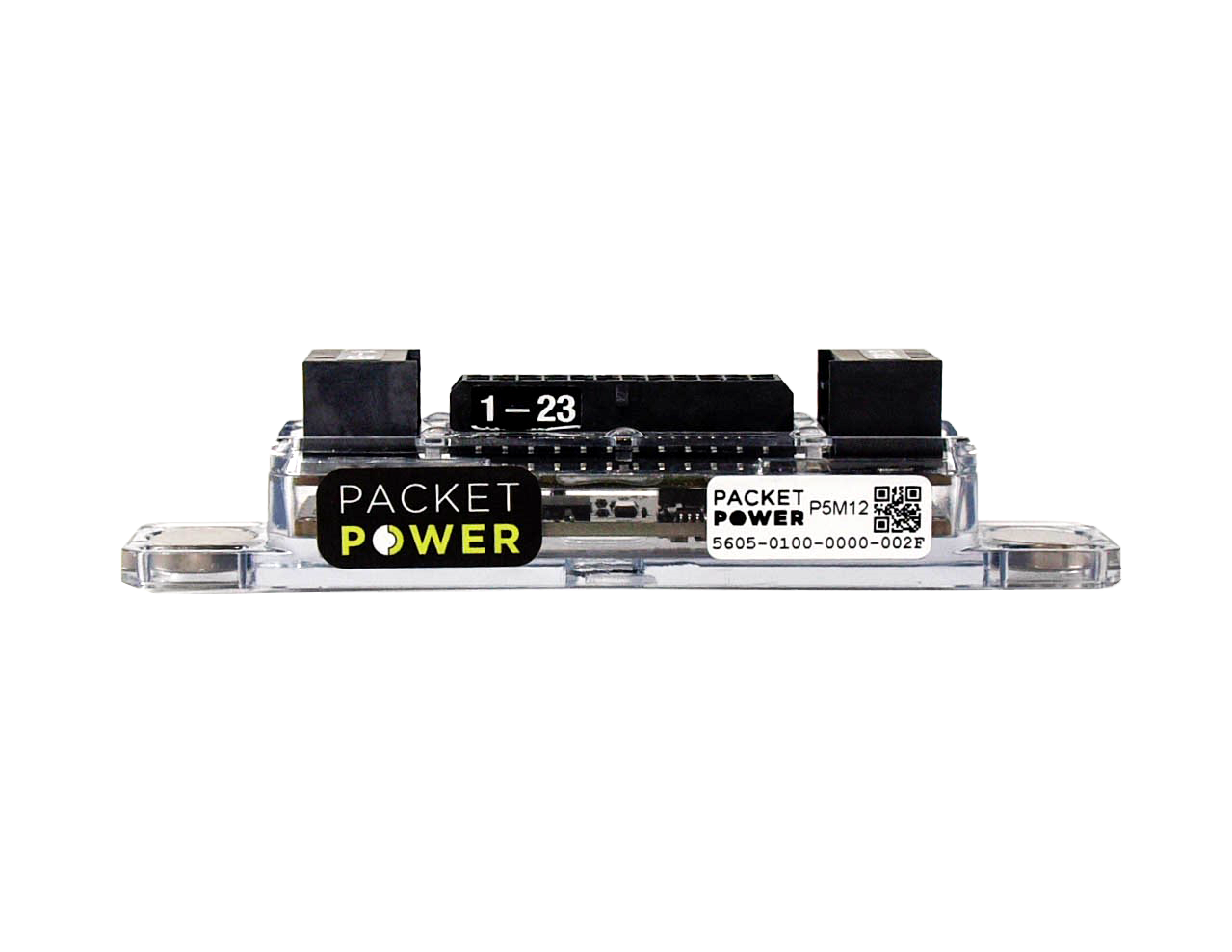
Each sensor interface is paired with an identically labeled sensor harness used to connect current sensors.
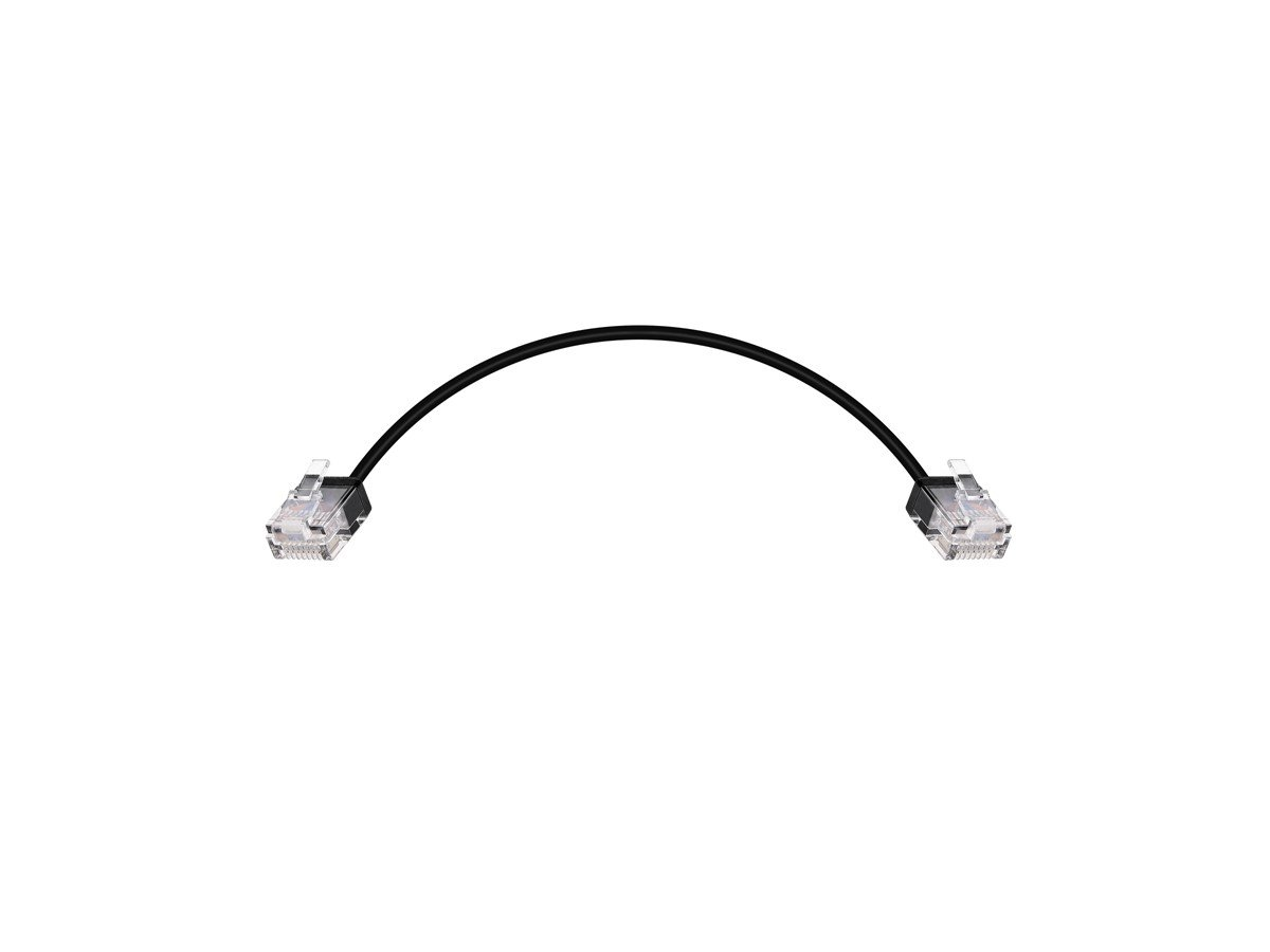
PPBUS connections
PPBUS connections are proprietary links used to connect the monitoring module and the sensor interfaces. PPBUS cables use standard RJ-45 connectors, however, standard network cabling should not be used since it may damage the system or degrade system performance. The connections between the monitoring module and sensor interfaces can be made in ANY order to ANY connector, as long as all sensor interfaces are connected to the monitoring module.
Current sensors
HDPM support a complete set of sensors of varying current rating and physical sizes. Solid-core, split-core and Rogowski coil sensor types are all supported. Multiple sizes of current sensors can be used with a single system. Please contact Packet Power to access the on-line configurator to customize your order.
